
Chapter 13
Aircraft Landing Gear Systems
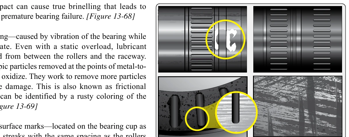
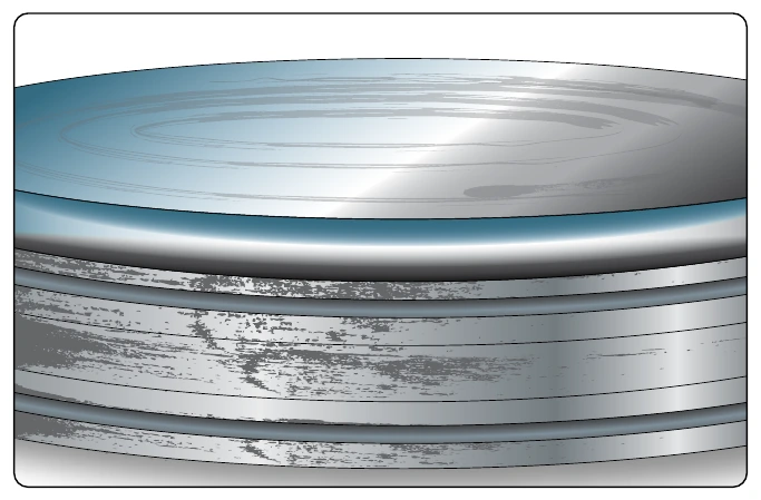
Etching and corrosion—caused when water and the damage caused by water penetrates the surface treatment of the bearing element. It appears as a reddish/brown discoloration. [Figure 13-71]
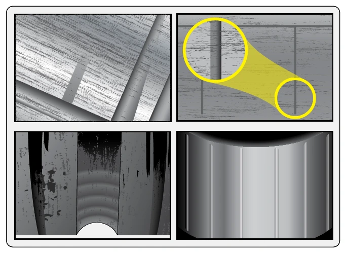
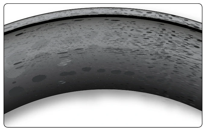
Bruising—caused by fine particle contamination possibly from a bad seal or improper maintenance of bearing cleanliness. It leaves a less than smooth surface on the bearing cup. [Figure 13-72]
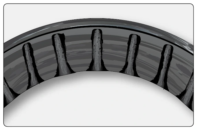
The bearing cup does not require removal for inspection; however, it must be firmly seated in the wheel half boss. There should be no evidence that a cup is loose or able to spin. [Figure 13-73] The cup is usually removed by heating the wheel in a controlled oven and pressing it out or tapping it out with a non-metallic drift. The installation procedure is similar. The wheel is heated, and the cup is cooled with dry ice before it is tapped into place with a non-metallic hammer or drift. The outside of the race is often sprayed with primer before insertion. Consult the wheel manufacturer’s maintenance manual for specific instructions.
Bearing Handling & Lubrication
Handling of bearings is of the utmost importance. Contamination, moisture, and vibration, even while the bearing is in a static state, can ruin a bearing. Avoid conditions where these may affect bearings and be sure to install and torque bearings into place according manufacturer’s instructions.
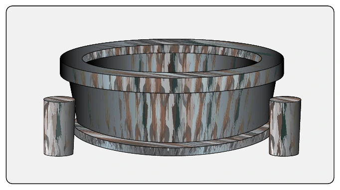
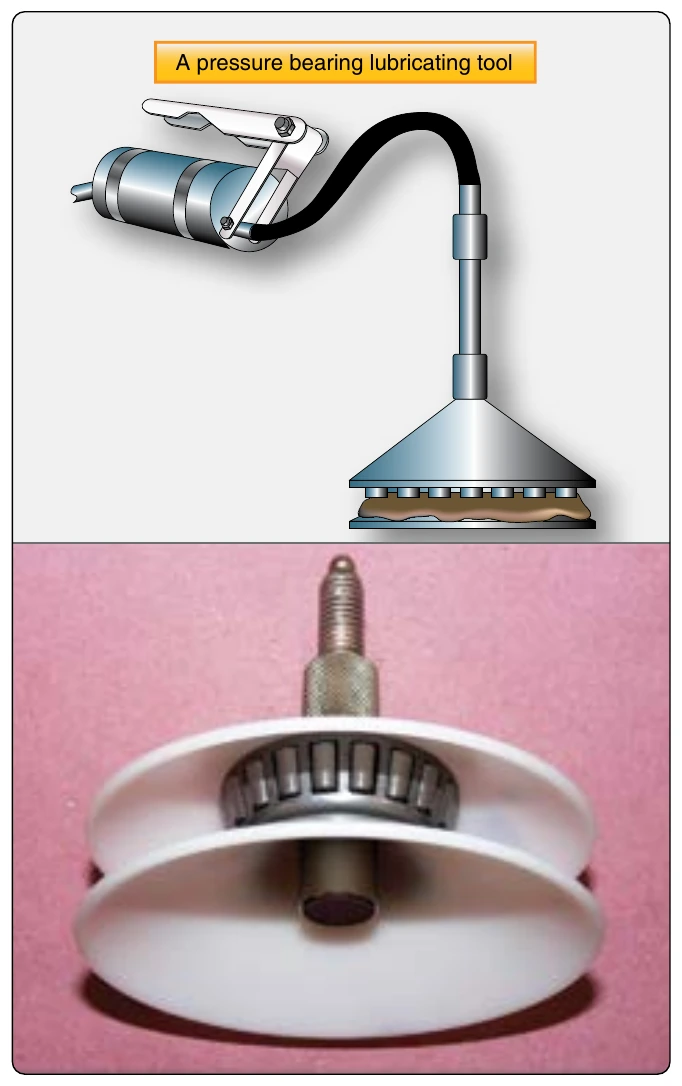
Proper lubrication is a partial deterrent to negative environmental impacts on a bearing. Use the lubricant recommended by the manufacturer. Use of a pressure bearing packing tool or adapter is also recommended as the best method to remove any contaminants from inside the bearing that may have remained after cleaning. [Figure 13-74]
Inspection of the Wheel Halves
A thorough visual inspection of each wheel half should be conducted for discrepancies specified in the wheel manufacturer’s maintenance data. Use of a magnifying glass is recommended. Corrosion is one of the most common problems encountered while inspecting wheels. Locations where moisture is trapped should be checked closely. It is possible to dress out some corrosion according to the manufacturer’s instructions. An approved protective surface treatment and finish must be applied before returning the wheel to service. Corrosion beyond stated limits is cause for rejection of the wheel.
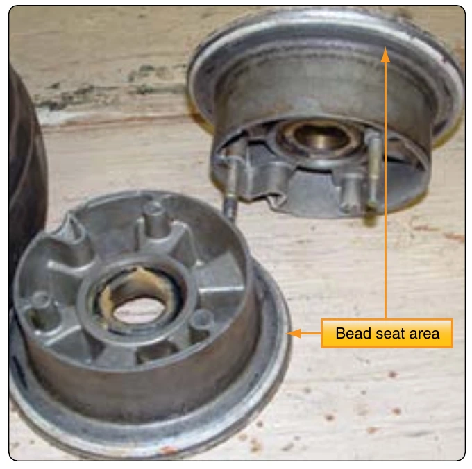
In addition to corrosion, cracks in certain areas of the wheel are particularly prevalent. One such area is the bead seat area. [Figure 13-75] The high stress of landing is transferred to the wheel by the tire in this contact area. Hard landings produce distortion or cracks that are very difficult to detect. This is a concern on all wheels and is most problematic in high-pressure, forged wheels. Dye penetrant inspection is generally ineffective when checking for cracks in the bead area. There is a tendency for cracks to close up tightly once the tire is dismounted, and the stress is removed from the metal. Eddy current inspection of the bead seat area is required. Follow the wheel manufacturer’s instruction when performing the eddy current check.
The wheel brake disc drive key area is another area in which cracks are common. The forces experienced when the keys drive the disc against the stopping force of the brakes are high. Generally, a dye penetrant test is sufficient to reveal cracks in this area. All drive keys should be secure with no movement possible. No corrosion is permitted in this area. [Figure 13-76]
Wheel Tie Bolt Inspection
Wheel half tie bolts are under great stress while in service and require inspection. The tie bolts stretch and change dimension usually at the threads and under the bolt head. These are areas where cracks are most common. Magnetic particle inspection can reveal these cracks. Follow the maintenance