
Chapter 13
Aircraft Landing Gear Systems
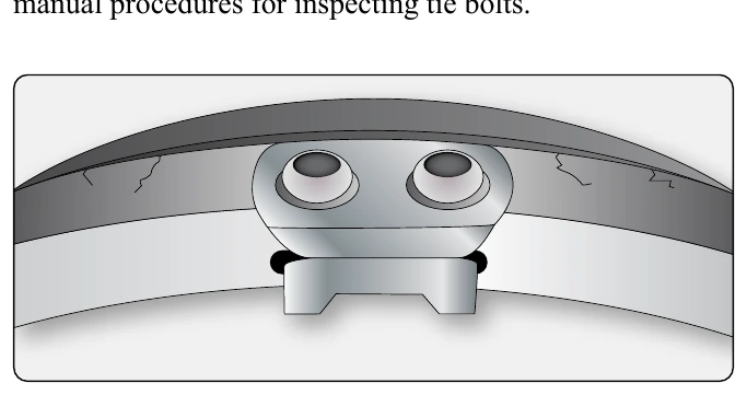
Key & Key Screw Inspection
On most aircraft inner wheel halves, keys are screwed or bolted to the wheel to drive the brake disc(s). The drive keys are subject to extreme forces when the brakes are applied. As mentioned, there should be no movement between the wheel and the keys. The bolts should be checked for security, and the area around the keys should be inspected for cracks. There is also a limitation on how worn the keys can be since too much wear allows excessive movement. The wheel manufacturer’s maintenance instructions should be used to perform a complete inspection of this critical area.
Fusible Plug Inspection
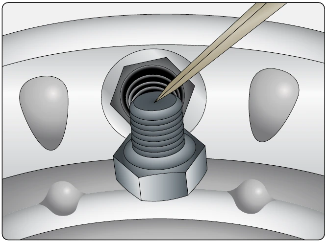
Fusible plugs or thermal plugs must be inspected visually. These threaded plugs have a core that melts at a lower temperature than the outer part of the plug. This is to release air from the tire should the temperature rise to a dangerous level. A close inspection should reveal whether any core has experienced deformation that might be due to high temperature. If detected, all thermal plugs in the wheel should be replaced with new plugs. [Figure 13-77]
Balance Weights
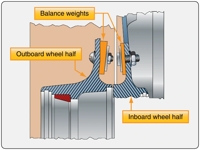
The balance of an aircraft wheel assembly is important. When manufactured, each wheel set is statically balanced. Weights are added to accomplish this if needed. They are a permanent part of the wheel assembly and must be installed to use the wheel. The balance weights are bolted to the wheel halves and can be removed when cleaning and inspecting the wheel. They must be re-fastened in their original position. When a tire is mounted to a wheel, balancing of the wheel and tire assembly may require that additional weights be added. These are usually installed around the circumference of the outside of the wheel and should not be taken as substitutes for the factory wheel set balance weights. [Figure 13-78]
Aircraft Brakes
Very early aircraft have no brake system to slow and stop the aircraft while it is on the ground. Instead, they rely on slow speeds, soft airfield surfaces, and the friction developed by the tail skid to reduce speed during ground operation. Brake systems designed for aircraft became common after World War I as the speed and complexity of aircraft increased, and the use of smooth, paved runway surfaces proliferated. All modern aircraft are equipped with brakes. Their proper functioning is relied upon for safe operation of the aircraft on the ground. The brakes slow the aircraft and stop it in a reasonable amount of time. They hold the aircraft stationary during engine run-up and, in many cases, steer the aircraft during taxi. On most aircraft, each of the main wheels is equipped with a brake unit. The nose wheel or tail wheel does not have a brake.
In the typical brake system, mechanical and/or hydraulic linkages to the rudder pedals allow the pilot to control the brakes. Pushing on the top of the right rudder pedal activates the brake on the right main wheel(s) and pushing on the top of the left rudder pedal operates the brake on the left main wheel(s). The basic operation of brakes involves converting the kinetic energy of motion into heat energy through the creation of friction. A great amount of heat is developed and forces on the brake system components are demanding. Proper adjustment, inspection, and maintenance of the brakes is essential for effective operation.
Types & Construction of Aircraft Brakes
Modern aircraft typically use disc brakes. The disc rotates with the turning wheel assembly while a stationary caliper resists the rotation by causing friction against the disc when the brakes are applied. The size, weight, and landing speed of the aircraft influence the design and complexity of the disc brake system. Single, dual, and multiple disc brakes are common types of brakes. Segmented rotor brakes are used on large aircraft. Expander tube brakes are found on older large aircraft. The use of carbon discs is increasing in the modern aviation fleet.
Single Disc Brakes
Small, light aircraft typically achieve effective braking using a single disc keyed or bolted to each wheel. As the wheel turns, so does the disc. Braking is accomplished by applying friction to both sides of the disc from a non-rotating caliper bolted to the landing gear axle flange. Pistons in the caliper housing under hydraulic pressure force wearable brake pads or linings against the disc when the brakes are applied. Hydraulic master cylinders connected to the rudder pedals supply the pressure when the upper halves of the rudder pedals are pressed.
Floating Disc Brakes
A floating disc brake is illustrated in Figure 13-79. A more detailed, exploded view of this type of brake is shown in
cylinders bored through the housing, but on other brakes this number may vary. Each cylinder accepts an actuating piston assembly comprised mainly of a piston, a return spring, and an automatic adjusting pin. Each brake assembly has six brake linings or pucks. Three are located on the ends of the pistons, which are in the outboard side of the caliper. They are designed to move in and out with the pistons and apply pressure to the outboard side of the disc. Three more linings are located opposite of these pucks on the inboard side of the caliper. These linings are stationary.
The brake disc is keyed to the wheel. It is free to move laterally in the key slots. This is known as a floating disc. When the brakes are applied, the pistons move out from the outboard cylinders and their pucks contact the disc. The disc slides slightly in the key slots until the inboard stationary pucks also contact the disc. The result is a fairly even amount of friction applied to each side of the disc and thus, the rotating motion is slowed.