
Chapter 13
Aircraft Landing Gear Systems
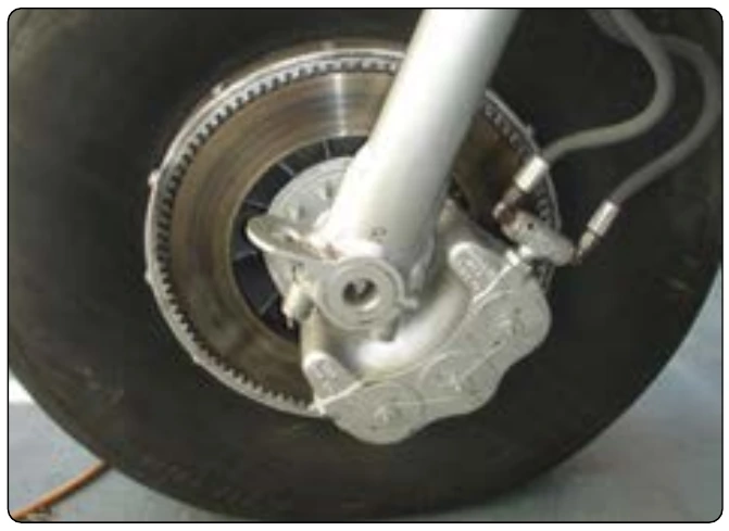
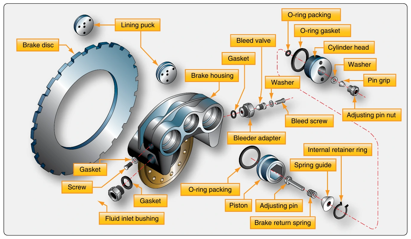
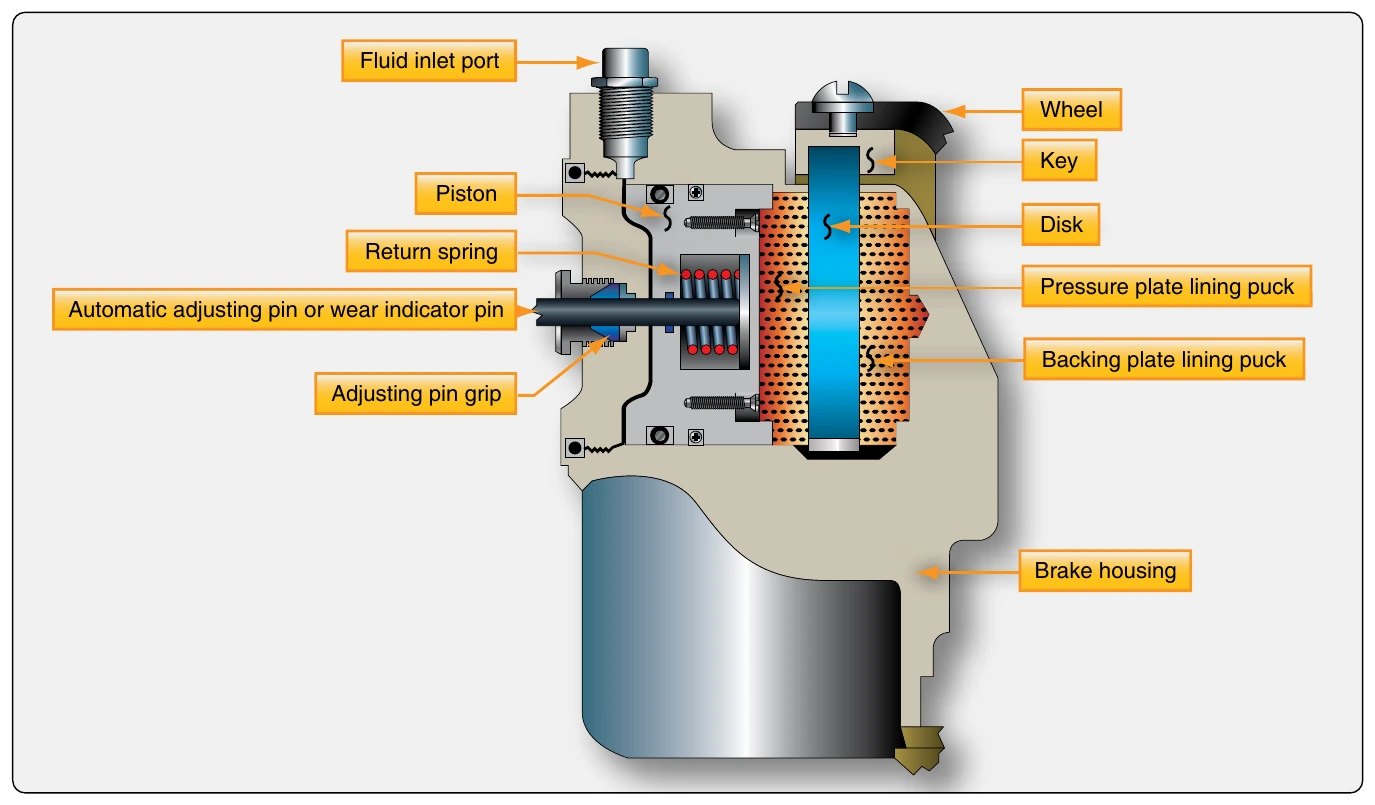
When brake pressure is released, the return spring in each piston assembly forces the piston back away from the disc. The spring provides a preset clearance between each puck and the disc. The self-adjusting feature of the brake maintains the same clearance, regardless of the amount of wear on the brake pucks. The adjusting pin on the back of each piston moves with the piston through a frictional pin grip. When brake pressure is relieved, the force of the return spring is sufficient to move the piston back away from the brake disc, but not enough to move the adjusting pin held by the friction of the pin grip. The piston stops when it contacts the head of the adjusting pin. Thus, regardless of the amount of wear, the same travel of the piston is required to apply the brake. The stem of the pin protruding through the cylinder head serves as a wear indicator. The manufacturer’s maintenance information states the minimum length of the pin that needs to be protruding for the brakes to be considered airworthy. [Figure 13-81]
The brake caliper has the necessary passages machined into it to facilitate hydraulic fluid movement and the application of pressure when the brakes are utilized. The caliper housing also contains a bleed port used by the technician to remove unwanted air from the system. Brake bleeding, as it is known, should be done in accordance with the manufacturer’s maintenance instructions.
Fixed-Disc Brakes
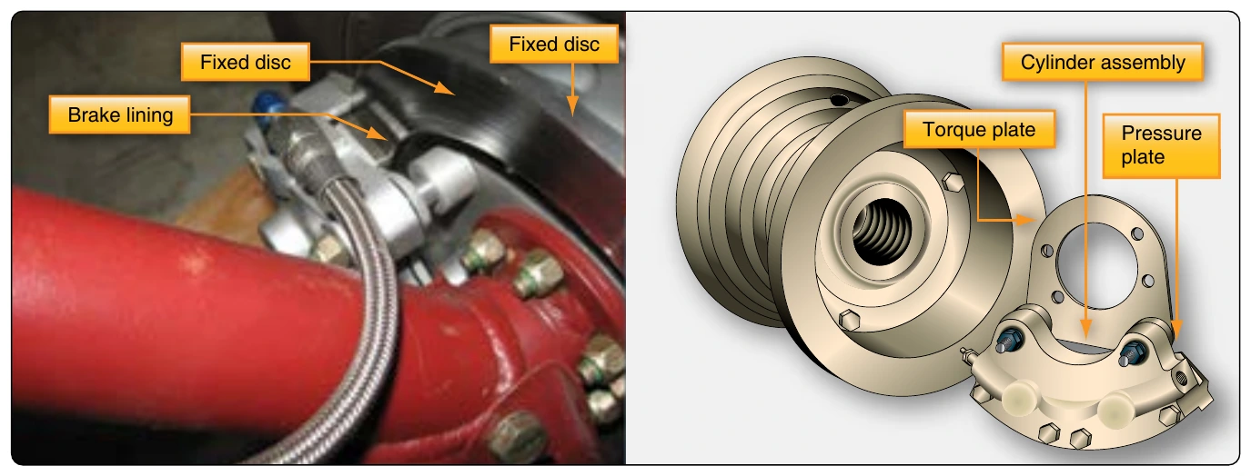
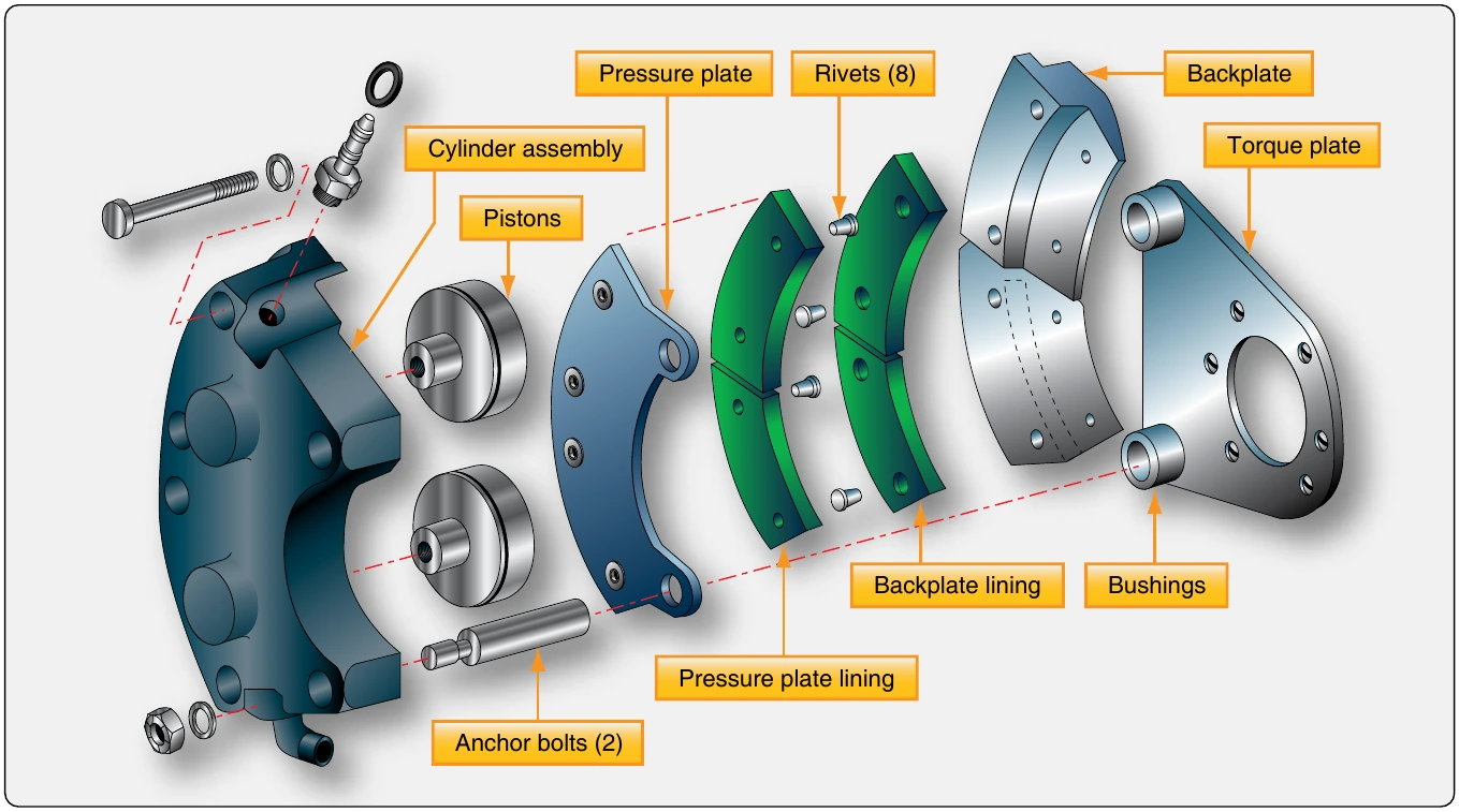
Even pressure must be applied to both sides of the brake disc to generate the required friction and obtain consistent wear properties from the brake linings. The floating disc accomplishes this as described above. It can also be accomplished by bolting the disc rigidly to the wheel and allowing the brake caliper and linings to float laterally when pressure is applied. This is the design of a common fixed-disc brake used on light aircraft. The brake is manufactured by the Cleveland Brake Company and is shown in Figure 13-82. An exploded detail view of the same type of brake is shown in Figure 13-83.
The fixed-disc, floating-caliper design allows the brake caliper and linings to adjust position in relationship to the disc. Linings are riveted to the pressure plate and backplate. Two anchor bolts that pass through the pressure plate are secured to the cylinder assembly. The other ends of the bolts are free to slide in and out of bushings in the torque plate, which is bolted to the axle flange. The cylinder assembly is bolted to the backplate to secure the assembly around the disc. When pressure is applied, the caliper and linings center on the disc via the sliding action of the anchor bolts in the torque plate bushings. This provides equal pressure to both sides of the disc to slow its rotation.
A unique feature of the Cleveland brake is that the linings can be replaced without removing the wheel. Unbolting the cylinder assembly from the backplate allows the anchor bolts to slide out of the torque plate bushings. The entire caliper assembly is then free and provides access to all of the components.
Maintenance requirements on all single disc brake systems are similar to those on brake systems of any type. Regular inspection for any damage and for wear on the linings and discs is required. Replacement of parts worn beyond limits is always followed by an operational check. The check is performed while taxiing the aircraft. The braking action for each main wheel should be equal with equal application of pedal pressure. Pedals should be firm, not soft or spongy, when applied. When pedal pressure is released, the brakes should release without any evidence of drag.
Dual-Disc Brakes
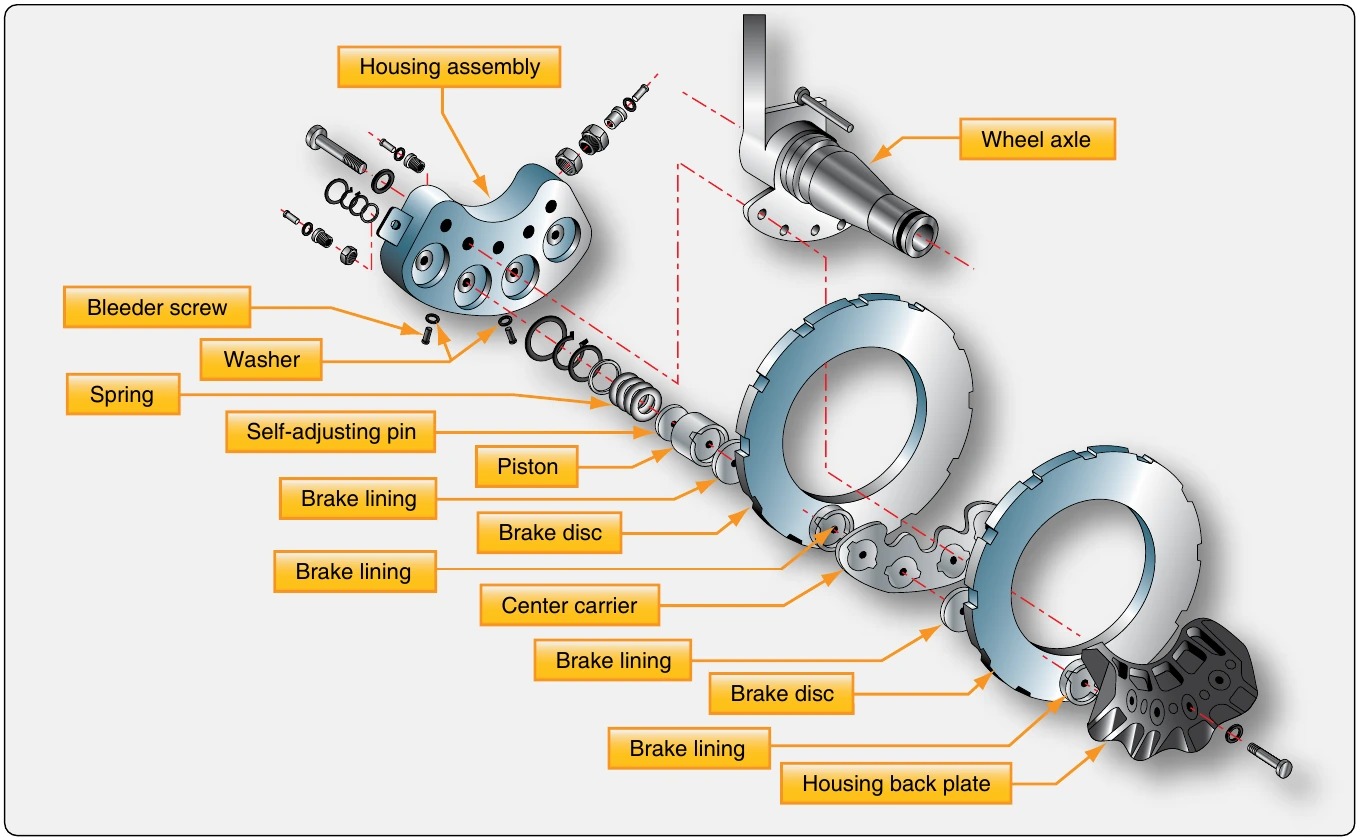
Dual-disc brakes are used on aircraft where a single disc on each wheel does not supply sufficient braking friction. Two discs are keyed to the wheel instead of one. A center carrier is located between the two discs. It contains linings on each side that contact each of the discs when the brakes are applied. The caliper mounting bolts are long and mount through the center carrier, as well as the backplate which bolts to the housing assembly. [Figure 13-84]
Multiple-Disc Brakes
Large, heavy aircraft require the use of multiple-disc brakes. Multiple-disc brakes are heavy duty brakes designed for use with power brake control valves or power boost master cylinders, which is discussed later in this chapter. The brake assembly consists of an extended bearing carrier similar to a torque tube type unit that bolts to the axle flange. It supports the various brake parts, including an annular cylinder and piston, a series of steel discs alternating with copper or bronze-plated discs, a backplate, and a backplate retainer. The steel stators are keyed to the bearing carrier, and the copper or bronze plated rotors are keyed to the rotating wheel. Hydraulic pressure applied to the piston causes the entire stack of stators and rotors to be compressed. This creates enormous friction and heat and slows the rotation of the wheel. [Figure 13-85]
As with the single and dual-disc brakes, retracting springs return the piston into the housing chamber of the bearing carrier when hydraulic pressure is relieved. The hydraulic fluid exits the brake to the return line through an automatic adjuster. The adjuster traps a predetermined amount of fluid in the brakes that is just sufficient to provide the correct clearances between the rotors and stators. [Figure 13-86] Brake wear is typically measured with a wear gauge that is not part of the brake assembly. These types of brake are typically found on older transport category aircraft. The rotors and stators are relatively thin, only about 1⁄8-inch thick. They do not dissipate heat very well and have a tendency to warp.
Segmented Rotor-Disc Brakes
The large amount of heat generated while slowing the rotation of the wheels on large and high-performance aircraft is problematic. To better dissipate this heat, segmented rotor-disc brakes have been developed. Segmented rotor-disc brakes are multiple-disc brakes but of more modern design than the type discussed earlier. There are many variations. Most feature numerous elements that aid in the control and dissipation of heat. Segmented rotor-disc brakes are heavy-duty brakes especially adapted for use with the high pressure hydraulic systems of power brake systems. Braking is accomplished by means of several sets of stationary, high friction type brake linings that make contact with rotating segments. The rotors are constructed with slots or in sections with space between them, which helps dissipate heat and give the brake its name. Segmented rotor multiple-disc brakes are the standard brake used on high performance and air carrier aircraft. An exploded view of one type of segmented rotor brake assembly is shown in Figure 13-87.