
Chapter 13
Aircraft Landing Gear Systems
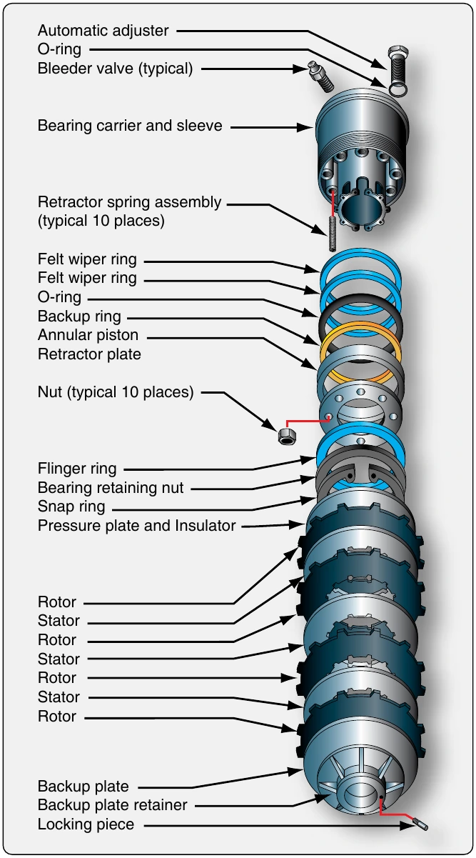
The description of a segmented rotor brake is very similar to the multiple-disc type brake previously described. The brake assembly consists of a carrier, a piston and piston cup seal, a pressure plate, an auxiliary stator plate, rotor segments, stator plates, automatic adjusters, and a backing plate.
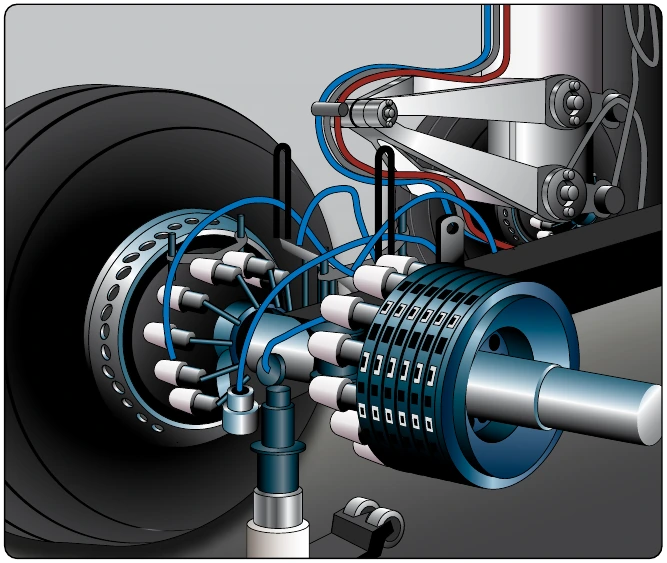
The carrier assembly, or brake housing with torque tube, is the basic unit of the segmented rotor brake. It is the part that attaches to the landing gear shock strut flange upon which the other components of the brake are assembled. On some brakes, two grooves or cylinders are machined into the carrier to receive the piston cups and pistons. [Figure 13-87] Most segmented rotor-disc brakes have numerous individual cylinders machined into the brake housing into which fit the same number of actuating pistons. Often, these cylinders are supplied by two different hydraulic sources, alternating every other cylinder from a single source. If one source fails, the brake still operates sufficiently on the other. [Figure 13-88] External fittings in the carrier or brake housing admit the hydraulic fluid. A bleed port can also be found.
A pressure plate is a flat, circular, high-strength steel, non-rotating plate notched on the inside circumference to fit over the stator drive sleeves or torque tube spines. The brake actuating pistons contact the pressure plate. Typically, an insulator is used between the piston head and the pressure plate to impede heat conduction from the brake discs. The pressure plate transfers the motion of the pistons to the stack of rotors and stators that compress to slow the rotation of the wheels. On most designs, brake lining material attached directly to the pressure plate contacts the first rotor in the stack to transfer the motion of the piston(s). [Figure 13-87] An auxiliary stator plate with brake lining material on the side opposite the pressure plate can also be used.
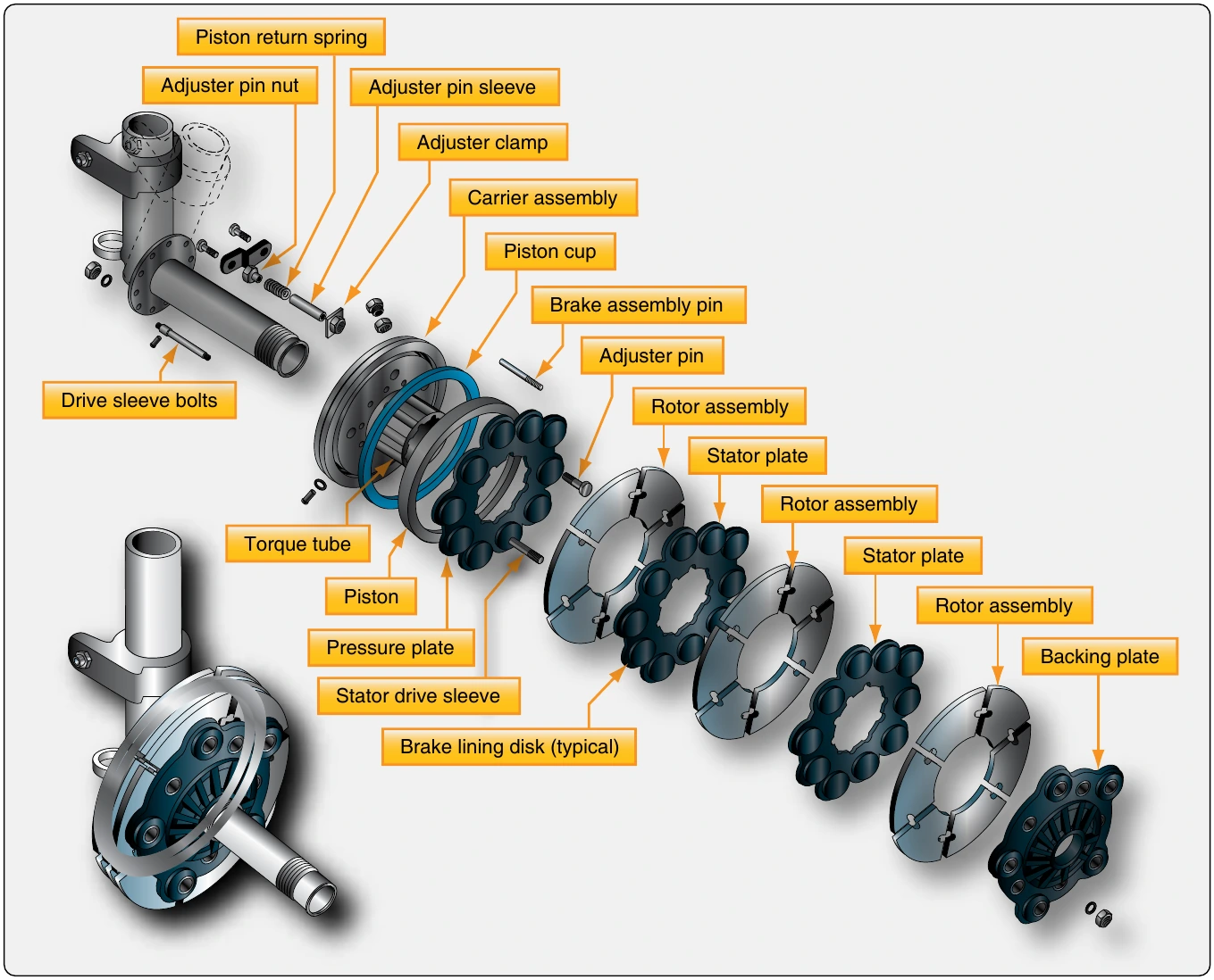
Any number of alternating rotors and stators are sandwiched under hydraulic pressure against the backing plate of the brake assembly when the brakes are applied. The backing plate is a heavy steel plate bolted to the housing or torque tube at a fixed dimension from the carrier housing. In most cases, it has brake lining material attached to it and contacts the last rotor in the stack. [Figure 13-87]
Stators are flat plates notched on the internal circumference to be held stationary by the torque tube spines. They have wearable brake lining material riveted or adhered to each side to make contact with adjacent rotors. The liner is typically constructed of numerous isolated blocks. [Figure 13-87] The space between the liner blocks aids in the dissipation of heat. The composition of the lining materials vary. Steel is often used.
Rotors are slit or segmented discs that have notches or tangs in the external circumference that key to the rotating wheel. Slots or spaces between sections of the rotor create segments that allow heat to dissipate faster than it would if the rotor was solid. They also allow for expansion and prevent warping. [Figure 13-87] Rotors are usually steel to which a frictional surface is bonded to both sides. Typically, sintered metal is used in creating the rotor contact surface.
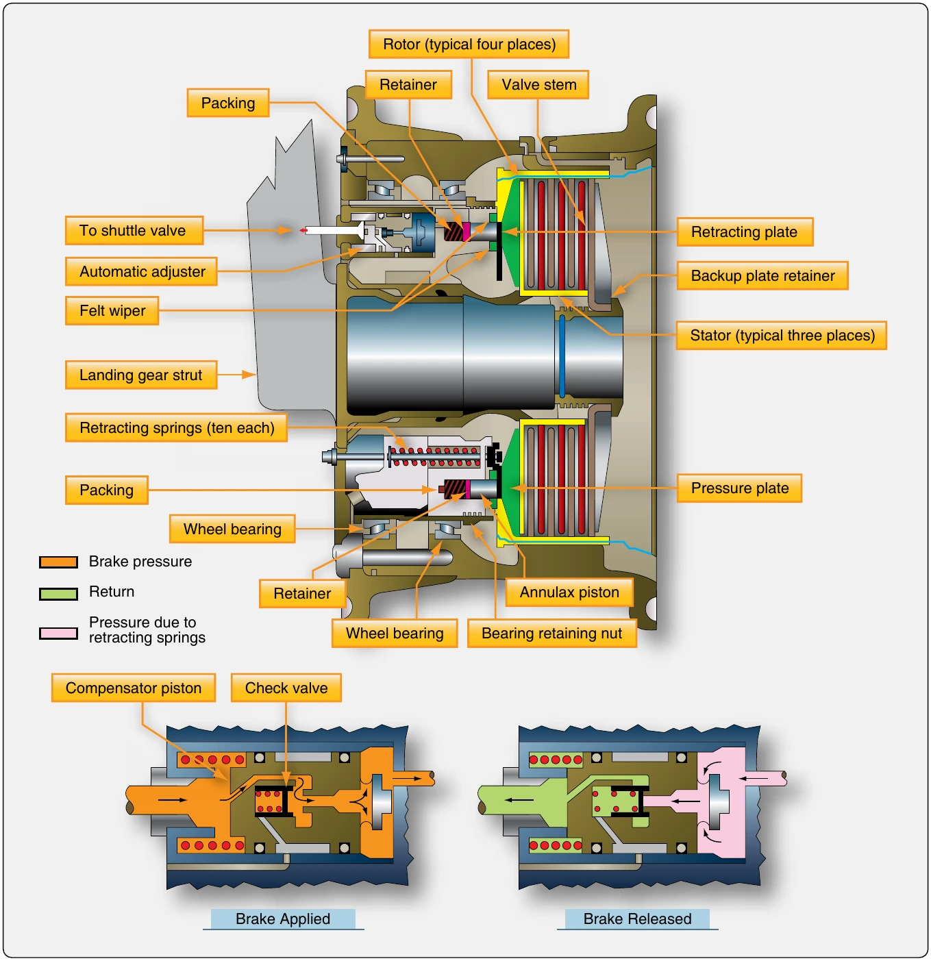
Segmented multiple-disc brakes use retraction spring assemblies with auto clearance adjusters to pull the backplate away from the rotor and stator stack when brake pressure is removed. This provides clearance so the wheel can turn unimpeded by contact friction between the brake parts but keeps the units in close proximity for rapid contact and braking when the brakes are applied. The number of retraction devices varies with brake design. Figure 13-89 illustrates a brake assembly used on a Boeing 737 transport category aircraft. In the cutaway view, the number and locations of the auto adjustment retraction mechanisms can be seen. Details of the mechanisms are also shown.
Instead of using a pin grip assembly for auto adjustment, an adjuster pin, ball, and tube operate in the same manner. They move out when brake pressure is applied, but the ball in the tube limits the amount of the return to that equal to the brake lining wear. Two independent wear indicators are used on the brake illustrated. An indicator pin attached to the backplate protrudes through the carrier. The amount that it protrudes with the brakes applied is measured to ascertain if new linings are required.
Carbon Brakes
The segmented multiple-disc brake has given many years of reliable service to the aviation industry. It has evolved through time in an effort to make it lightweight and to dissipate the frictional heat of braking in a quick, safe manner. The latest iteration of the multiple-disc brake is the carbon-disc brake. It is currently found on high performance and air carrier aircraft. Carbon brakes are so named because carbon fiber materials are used to construct the brake rotors. [Figure 13-90]
Carbon brakes are approximately forty percent lighter than conventional brakes. On a large transport category aircraft, this alone can save several hundred pounds in aircraft weight. The carbon fiber discs are noticeably thicker than sintered steel rotors but are extremely light. They are able to withstand temperatures fifty percent higher than steel component brakes. The maximum designed operating temperature is limited by the ability of adjacent components to withstand the high temperature. Carbon brakes have been shown to withstand two to three times the heat of a steel brake in non-aircraft applications. Carbon rotors also dissipate heat faster than steel rotors. A carbon rotor maintains its strength and dimensions at high temperatures. Moreover, carbon brakes last twenty to fifty percent longer than steel brakes, which results in reduced maintenance.
The only impediment to carbon brakes being used on all aircraft is the high cost of manufacturing. The price is expected to lower as technology improves and greater numbers of aircraft operators enter the market.
Expander Tube Brakes
An expander tube brake is a different approach to braking that is used on aircraft of all sizes produced in the 1930s–1950s. It is a lightweight, low pressure brake bolted to the axle flange that fits inside an iron brake drum. A flat, fabric-reinforced neoprene tube is fitted around the circumference of a wheel-like torque flange. The exposed flat surface of the expander tube is lined with brake blocks similar to brake lining material. Two flat frames bolt to the sides of the torque flange. Tabs on the frames contain the tube and allow evenly spaced torque bars to be bolted in place across the tube between each brake block. These prevent circumferential movement of the tube on the flange. [Figure 13-91]
The expander tube is fitted with a metal nozzle on the inner surface. Hydraulic fluid under pressure is directed through this fitting into the inside of the tube when the brakes are applied. The tube expands outward, and the brake blocks make contact with the wheel drum causing friction that slows the wheel. As hydraulic pressure is increased, greater friction develops. Semi-elliptical springs located under the torque bars return the expander tube to a flat position around the flange when hydraulic pressure is removed. The clearance between the expander tube and the brake drum is adjustable by rotating an adjuster on some expander tube brakes. Consult the manufacturer’s maintenance manual for the correct clearance setting. Figure 13-92 gives an exploded view of an expander tube brake, detailing its components.