
Chapter 13
Aircraft Landing Gear Systems
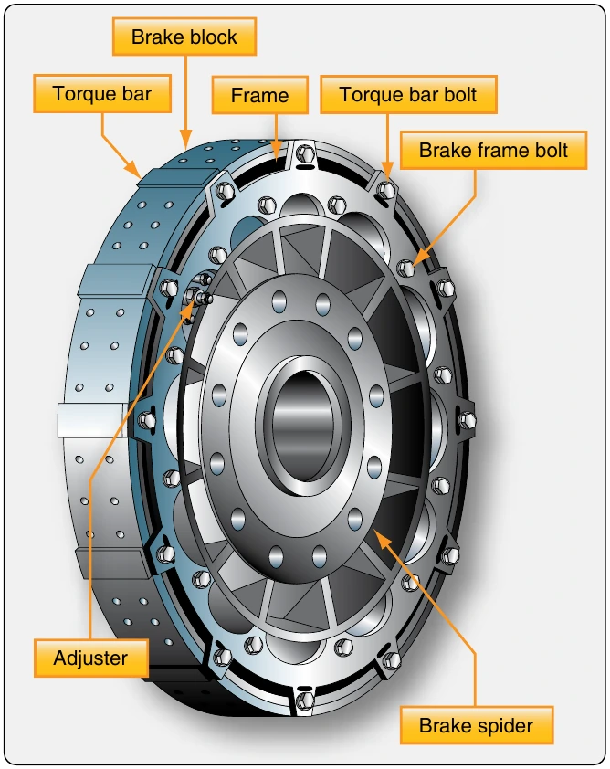
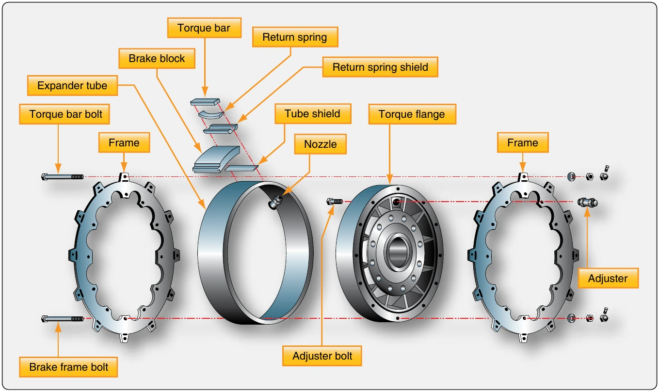
Expander tube brakes work well but have some drawbacks.
They tend to take a setback when cold. They also have a tendency to swell with temperature and leak. They may drag inside the drum if this occurs. Eventually, expander brakes were abandoned in favor of disc brake systems.
Brake Actuating Systems
The various brake assemblies, described in the previous section, all use hydraulic power to operate. Different means of delivering the required hydraulic fluid pressure to brake assemblies are discussed in this section. There are three basic actuating systems:
- An independent system not part of the aircraft main hydraulic system;
- A booster system that uses the aircraft hydraulic system intermittently when needed; and
- A power brake system that only uses the aircraft main. hydraulic system(s) as a source of pressure.
Systems on different aircraft vary, but the general operation is similar to those described.
Independent Master Cylinders
In general, small, light aircraft and aircraft without hydraulic systems use independent braking systems. An independent brake system is not connected in any way to the aircraft hydraulic system. Master cylinders are used to develop the necessary hydraulic pressure to operate the brakes. This is similar to the brake system of an automobile.
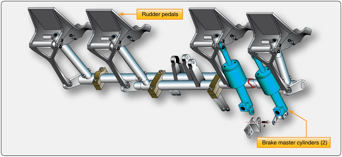
In most brake actuating systems, the pilot pushes on the tops of the rudder pedals to apply the brakes. A master cylinder for each brake is mechanically connected to the corresponding rudder pedal (i.e., right main brake to the right rudder pedal, left main brake to the left rudder pedal). [Figure 13-93] When the pedal is depressed, a piston inside a sealed fluid-filled chamber in the master cylinder forces hydraulic fluid through a line to the piston(s) in the brake assembly. The brake piston(s) push the brake linings against the brake rotor to create the friction that slows the wheel rotation. Pressure is increased throughout the entire brake systems and against the rotor as the pedal is pushed harder.
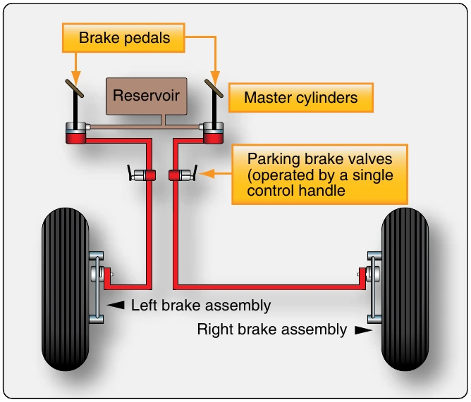
Many master cylinders have built-in reservoirs for the brake hydraulic fluid. Others have a single remote reservoir that services both of the aircraft’s two master cylinders. [Figure 13-94] A few light aircraft with nose wheel steering have only one master cylinder that actuates both main wheel brakes. This is possible because steering the aircraft during taxi does not require differential braking. Regardless of the set-up, it is the master cylinder that builds up the pressure required for braking.
A master cylinder used with a remote reservoir is illustrated in Figure 13-95. This particular model is a Goodyear master cylinder. The cylinder is always filled with air-free, contaminant-free hydraulic fluid as is the reservoir and the line that connects the two together. When the top of the rudder pedal is depressed, the piston arm is mechanically moved forward into the master cylinder. It pushes the piston against the fluid, which is forced through the line to the brake. When pedal pressure is released, the return springs in the brake assembly retract the brake pistons back into the brake housing. The hydraulic fluid behind the pistons is displaced and must return to the master cylinder. As it does, a return spring in the master cylinder move the piston, piston rod and rudder pedal back to the original position (brake off, pedal not depressed). The fluid behind the master cylinder piston flows back into the reservoir. The brake is ready to be applied again.
Hydraulic fluid expands as temperature increases. Trapped fluid can cause a brake to drag against the rotor(s). Leaks may also result. When the brakes are not applied, fluid must be allowed to expand safely without causing these issues. A compensating port is included in most master cylinders to facilitate this. In the master cylinder in Figure 13-95, this port is opened when the piston is fully retracted. Fluid in the brake system is allowed to expand into the reservoir, which has the capacity to accept the extra fluid volume. The typical reservoir is also vented to the atmosphere to provide positive pressure on the fluid.
The forward side of the piston head contains a seal that closes off the compensating port when the brakes are applied so that pressure can build. The seal is only effective in the forward direction. When the piston is returning, or is fully retracted to the off position, fluid behind the piston is free to flow through piston head ports to replenish any fluid that may be lost downstream of the master cylinder. The aft end of the master cylinder contains a seal that prevents leakage at all times. A rubber boot fits over the piston rod and the aft end of the master cylinder to keep out dust.
A parking brake for this remote reservoir master cylinder brake system is a ratcheting mechanical device between the master cylinder and the rudder pedals. With the brakes applied, the ratchet is engaged by pulling the parking brake handle. To release the brakes, the rudder pedals are depressed further allowing the ratchet to disengage. With the parking brake set, any expansion of hydraulic fluid due to temperature is relieved by a spring in the mechanical linkage.