
Chapter 13
Aircraft Landing Gear Systems
A common requirement of all braking systems is for there to be no air mixed in with the hydraulic fluid. Since air is compressible and hydraulic fluid essentially is not, any air under pressure when the brakes are applied causes spongy brakes. The pedals do not feel firm when pushed down due to the air compressing. Brake systems must be bled to remove all air from the system. Instructions for bleeding the brakes are in the manufacturer’s maintenance information. Brake systems equipped with Goodyear master cylinders must be bled from the top down to ensure any air trapped behind the master cylinder piston is removed.
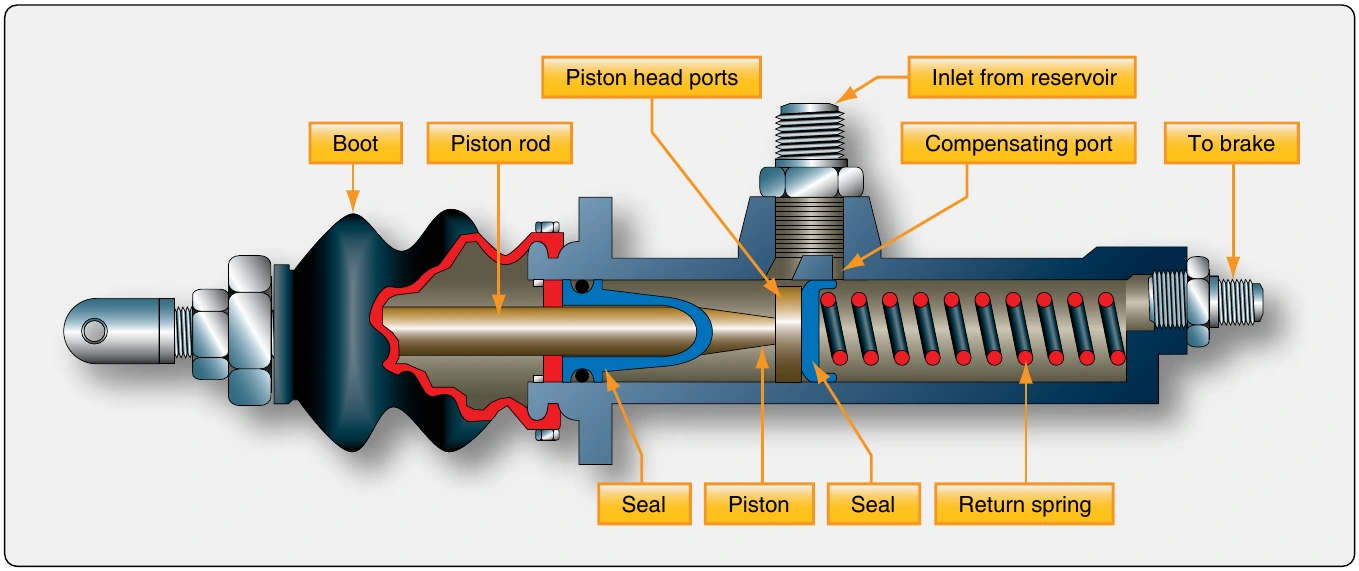
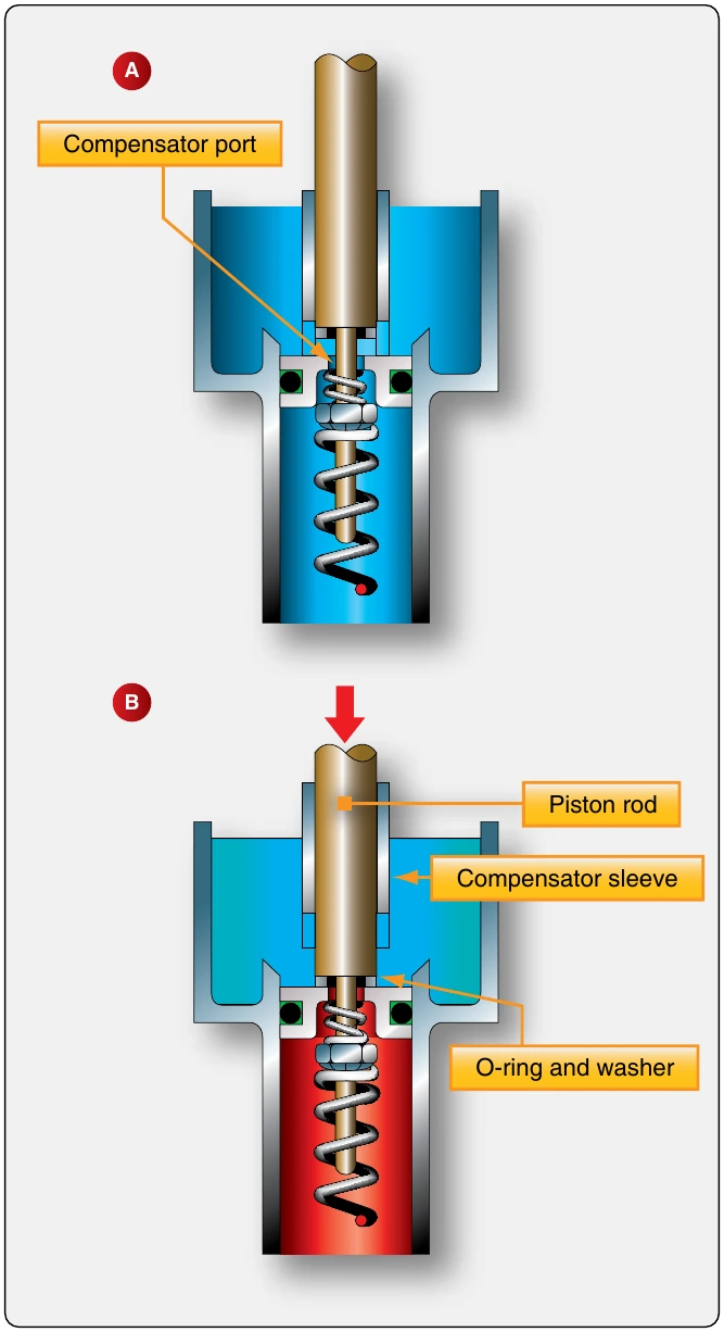
An alternative common arrangement of independent braking systems incorporates two master cylinders, each with its own integral fluid reservoir. Except for the reservoir location, the brake system is basically the same as just described. The master cylinders are mechanically linked to the rudder pedals as before. Depressing the top of a pedal causes the piston rod to push the piston into the cylinder forcing the fluid out to the brake assembly. The piston rod rides in a compensator sleeve and contains an O-ring that seals the rod to the piston when the rod is moved forward. This blocks the compensating ports. When released, a spring returns the piston to its original position which refills the reservoir as it returns. The rod end seal retracts away from the piston head allowing a free flow of fluid from the cylinder through the compensating ports in the piston to the reservoir. [Figure 13-96]
The parking brake mechanism is a ratcheting type that operates as described. A servicing port is supplied at the top of the master cylinder reservoir. Typically, a vented plug is installed in the port to provide positive pressure on the fluid.
Boosted Brakes
In an independent braking system, the pressure applied to the brakes is only as great as the foot pressure applied to the top of the rudder pedal. Boosted brake actuating systems augment the force developed by the pilot with hydraulic system pressure when needed. The boost is only during heavy braking. It results in greater pressure applied to the brakes than the pilot alone can provide. Boosted brakes are used on medium and larger aircraft that do not require a full power brake actuating system.
A boosted brake master cylinder for each brake is mechanically attached to the rudder pedals. However, the boosted brake master cylinder operates differently. [Figure 13-97]
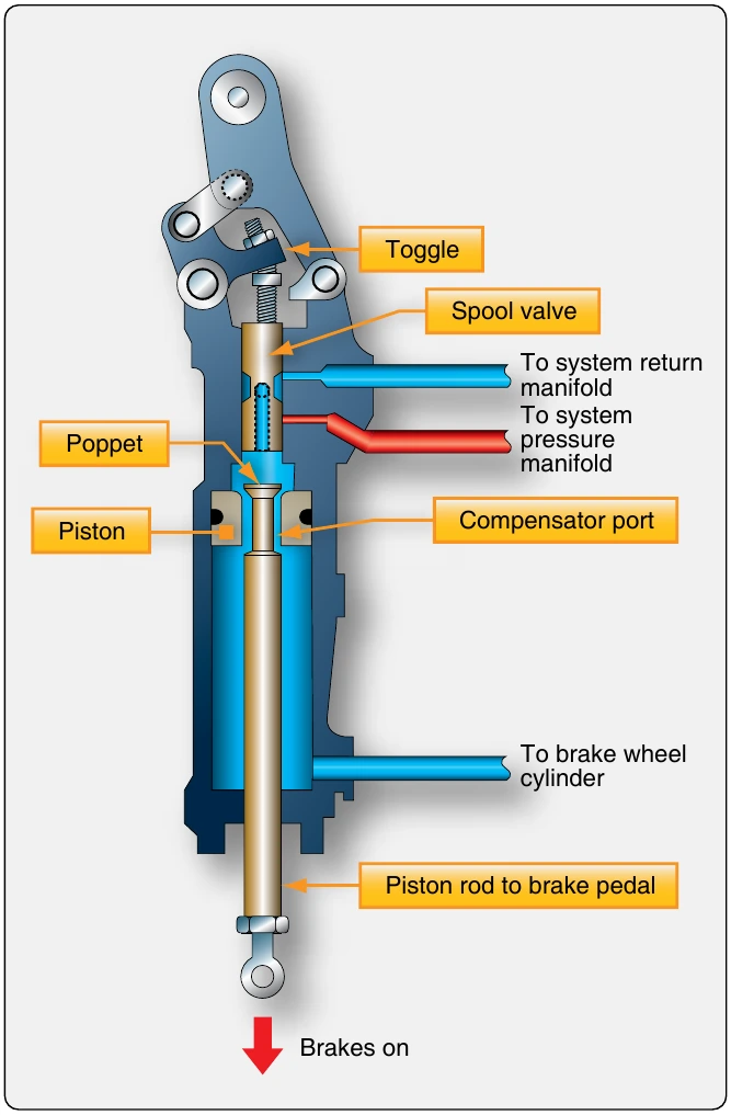
When the brakes are applied, the pressure from the pilot’s foot through the mechanical linkage moves the master cylinder piston in the direction to force fluid to the brakes. The initial movement closes the compensator poppet used to provide thermal expansion relief when the brakes are not applied. As the pilot pushes harder on the pedal, a spring-loaded toggle moves a spool valve in the cylinder. Aircraft hydraulic system pressure flows through the valve to the back side of the piston. Pressure is increased, as is the force developed to apply the brakes.
When the pedal is released, the piston rod travels in the opposite direction, and the piston returns to the piston stop. The compensating poppet reopens. The toggle is withdrawn from the spool via linkages, and fluid pushes the spool back to expose the system return manifold port. System hydraulic fluid used to boost brake pressure returns through the port.
Power Brakes
Large and high-performance aircraft are equipped with power brakes to slow, stop, and hold the aircraft. Power brake actuating systems use the aircraft hydraulic system as the source of power to apply the brakes. The pilot presses on the top of the rudder pedal for braking as with the other actuating systems. The volume and pressure of hydraulic fluid required cannot be produced by a master cylinder. Instead, a power brake control valve or brake metering valve receives the brake pedal input either directly or through linkages.
The valve meters hydraulic fluid to the corresponding brake assembly in direct relation to the pressure applied to the pedal.
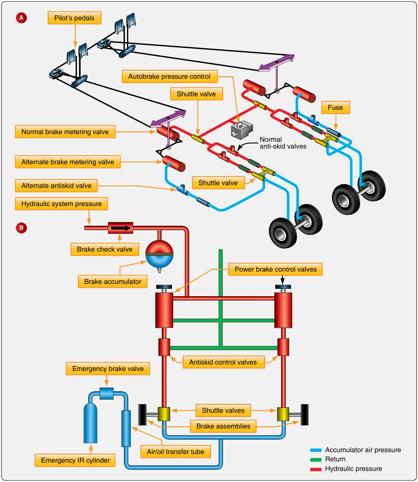
Many power brake system designs are in use. Most are similar to the simplified system illustrated in Figure 13-98A. Power brake systems are constructed to facilitate graduated brake pressure control, brake pedal feel, and the necessary redundancy required in case of hydraulic system failure. Large aircraft brake systems integrate anti-skid detection and correction devices. These are necessary because wheel skid is difficult to detect on the flight deck without sensors. However, a skid can be quickly controlled automatically through pressure control of the hydraulic fluid to the brakes. Hydraulic fuses are also commonly found in power brake systems. The hostile environment around the landing gear increases the potential for a line to break or sever, a fitting to fail, or other hydraulic system malfunctions to occur where hydraulic fluid is lost en route to the brake assemblies. A fuse stops any excessive flow of fluid when detected by closing to retain the remaining fluid in the hydraulic system. Shuttle valves are used to direct flow from optional sources of fluid, such as in redundant systems or during the use of an emergency brake power source. An airliner power brake system is illustrated in Figure 13-98B.
Brake Control Valve/Brake Metering Valve
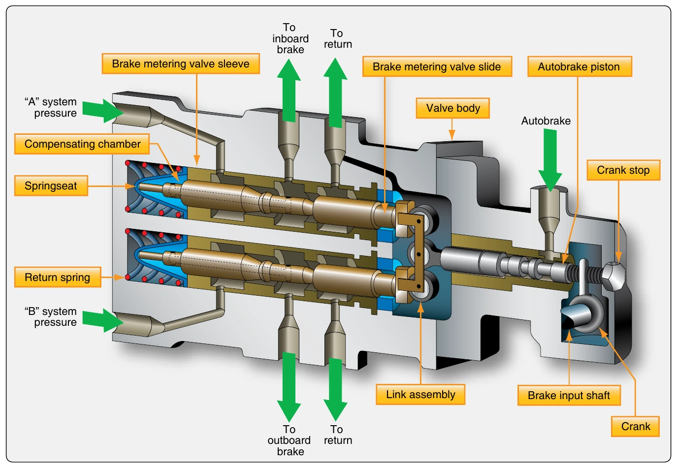
The key element in a power brake system is the brake control valve, sometimes called a brake metering valve. It responds to brake pedal input by directing aircraft system hydraulic fluid to the brakes. As pressure is increased on the brake pedal, more fluid is directed to the brake causing a higher pressure and greater braking action.
A brake metering valve from a Boeing 737 is illustrated in