
Chapter 13
Aircraft Landing Gear Systems
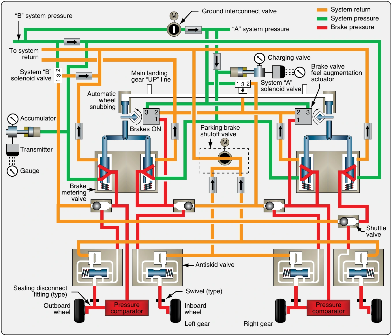
in Figure 13-100. Two sources of hydraulic pressure provide redundancy in this brake system. A brake input shaft, connected to the rudder/brake pedal through mechanical linkages, provides the position input to the metering valve. As in most brake control valves, the brake input shaft moves a tapered spool or slide in the valve so that it allows hydraulic system pressure to flow to the brakes. At the same time, the slide covers and uncovers access to the hydraulic system return port as required.
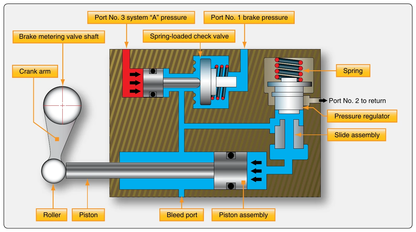
When the rudder/brake pedal is depressed, the slide in the metering valve moves to the left. [Figure 13-99] It covers the return port so pressure can build in the brake system. The hydraulic supply pressure chamber is connected to the brake system pressure chamber by the movement of the slide, which due to its taper, unblocks the passage between these two. As the pedal is depressed further, the valve slide moves farther to the left. This enables more fluid to flow to the brakes due to the narrowing shape of the slide. Brake pressure increases with the additional fluid. A passage in the slide directs brake pressure fluid into a compensating chamber at the end of the slide. This acts on the end of the slide creating a return force that counters the initial slide movement and gives feel to the brake pedal. As a result, the pressure and return ports are closed and pressure proportional to the foot pressure on the pedal is held on the brakes. When the pedal is released, a return spring and compensating chamber pressure drive the slide to the right into its original position (return port open, supply pressure chamber and brake pressure chambers blocked from each other).
The metering valve operates as described simultaneously for the inboard and the outboard brakes. [Figure 13-99] The design of the link assembly is such that a single side of the metering valve can operate even if the other fails. Most brake control valves and metering valves function in a similar manner, although many are single units that supply only one brake assembly.
The auto brake, referenced in the metering valve diagram, is connected into the landing gear retraction hydraulic line. Pressurized fluid enters this port and drives the slide slightly to the left to apply the brakes automatically after takeoff. This stops the wheels from rotating when retracted into the wheel wells. Auto brake pressure is withheld from this port when the landing gear is fully stowed since the retraction system is depressurized.
The majority of the rudder/brake pedal feel is supplied by the brake control or brake metering valve in a power brake system. Many aircraft refine the feel of the pedal with an additional feel unit. The brake valve feel augmentation unit, in the above system, uses a series of internal springs and pistons of various sizes to create a force on the brake input shaft movement. This provides feel back through the mechanical linkages consistent with the amount of rudder/brake pedal applied. The request for light braking with slight pedal depression results in a light feel to the pedal and a harder resistance feel when the pedals are pushed harder during heavy braking. [Figure 13-101]
Emergency Brake Systems
As can be seen in Figure 13-100, the brake metering valves not only receive hydraulic pressure from two separate hydraulic systems, they also feed two separate brake assemblies. Each main wheel assembly has two wheels. The inboard wheel brake and the outboard wheel brake, located in their respective wheel rims, are independent from each other. In case of hydraulic system failure or brake failure, each is independently supplied to adequately slow and stop the aircraft without the other. More complicated aircraft may involve another hydraulic system for back-up or use a similar alternation of sources and brake assemblies to maintain braking in case of hydraulic system or brake failure.
by independent hydraulic sources. This is another method of redundancy particularly suitable on, but not limited to, single main wheel aircraft.
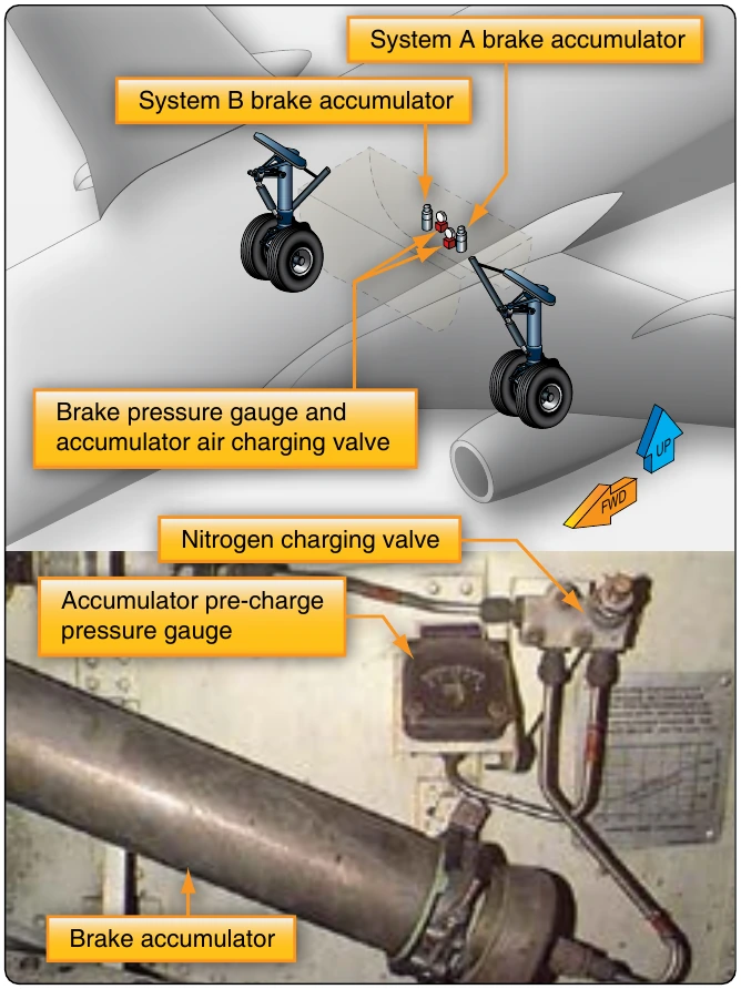
In addition to supply system redundancy, the brake accumulator is also an emergency source of power for the brakes in many power brake systems. The accumulator is pre-charged with air or nitrogen on one side of its internal diaphragm. Enough hydraulic fluid is contained on the other side of the diaphragm to operate the brakes in case of an emergency. It is forced out of the accumulator into the brakes through the system lines under enough stored pressure to slow the aircraft. Typically, the accumulator is located upstream of the brake control/metering valve to capitalize on the control given by the valve. [Figure 13-102]
Some simpler power brake systems may use an emergency source of brake power that is delivered directly to the brake assemblies and bypasses the remainder of the brake system completely. A shuttle valve immediately upstream of the brake units shifts to accept this source when pressure is lost from the primary supply sources. Compressed air or nitrogen is sometimes used. A pre-charged fluid source can also be used as an alternate hydraulic source.
Parking Brake
The parking brake system function is a combined operation. The brakes are applied with the rudder pedals and a ratcheting system holds them in place when the parking brake lever on the flight deck is pulled. [Figure 13-103] At the same time, a shut-off valve is closed in the common return line from the brakes to the hydraulic system. This traps the fluid in the brakes holding the rotors stationary. Depressing the pedals further releases the pedal ratchet and opens the return line valve.
Brake Deboosters
Some aircraft brake assemblies that operate on aircraft hydraulic system pressure are not designed for such high pressure. They provide effective braking through a power brake system but require less than maximum hydraulic system pressure. To supply the lower pressure, a brake debooster cylinder is installed downstream of the control valve and anti-skid valve. [Figure 13-104] The debooster reduces some pressure from the control valve to within the working range of the brake assembly.
Brake deboosters are simple devices that use the application of force over different sized pistons to reduce pressure. [Figure 13-105] Their operation can be understood through the application of the following equation: