Chapter 14
Aircraft Fuel Systems
Low- and mid-wing single reciprocating engine aircraft cannot utilize gravity-feed fuel systems because the fuel tanks are not located above the engine. Instead, one or more pumps are used to move the fuel from the tanks to the engine. A common fuel system of this type is shown in
to a selector valve. However, fuel cannot be drawn from both tanks simultaneously; if the fuel is depleted in one tank, the pump would draw air from that tank instead of fuel from the full tank. Since fuel is not drawn from both tanks at the same time, there is no need to connect the tank vent spaces together.
From the selector valve (LEFT, RIGHT, or OFF), fuel flows through the main strainer where it can supply the engine primer. Then, it flows downstream to the fuel pumps. Typically, one electric and one engine-driven fuel pump are arranged in parallel. They draw the fuel from the tank(s) and deliver it to the carburetor. The two pumps provide redundancy. The engine-driven fuel pump acts as the primary pump. The electric pump can supply fuel should the other fail.
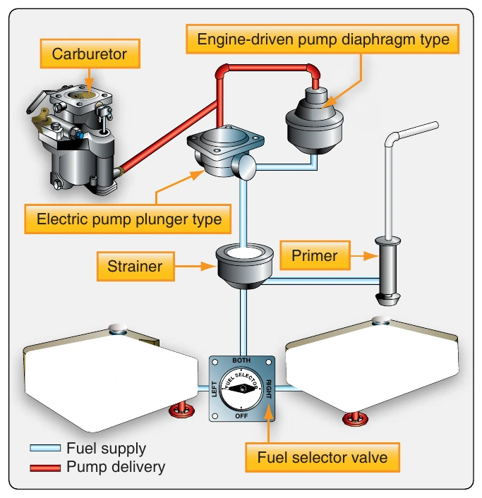
The electric pump also supplies fuel pressure while starting and is used to prevent vapor lock during flight at high altitude.
High-Wing Aircraft with Fuel Injection System
Some high-wing, high-performance, single-engine general aviation aircraft are equipped with a fuel system that features fuel injection rather than a carburetor. It combines gravity flow with the use of a fuel pump(s). The Teledyne- Continental system is an example. [Figure 14-14]
Fuel pressurized by an engine-driven pump is metered as a function of engine rpm on the Teledyne-Continental system. It is first delivered from the fuel tanks by gravity to two smaller accumulator or reservoir tanks. These tanks, one for each wing tank, consolidate the liquid fuel and have a relatively small airspace. They deliver fuel through a three-way selector valve (LEFT, RIGHT, or OFF). The selector valve also acts simultaneously as a diverter of air that has been separated out of the fuel in the engine-driven fuel pump and returned to the valve. It routes the air to the vent space above the fuel in the selected reservoir tank.
An electric auxiliary fuel pump draws fuel through the selector valve. It forces the fuel through the strainer, making it available for the primer pump and the engine-driven fuel pump. This pump is typically used for starting and as a backup should the engine-driven pump fail. It is controlled by a switch in the flight deck and does not need to be operating to allow the engine-driven fuel pump access to the fuel.
The engine-driven fuel pump intakes the pressurized fuel from the electrically driven pump or from the reservoir tanks if the electric pump is not operating. It supplies a higher-than-needed volume of fuel under pressure to the fuel control. Excess fuel is returned to the pump, which pumps it through the selector valve into the appropriate reservoir tank. Fuel vapor is also returned to tanks by the pump. The fuel control unit meters the fuel according to engine rpm and mixture control inputs from the flight deck.
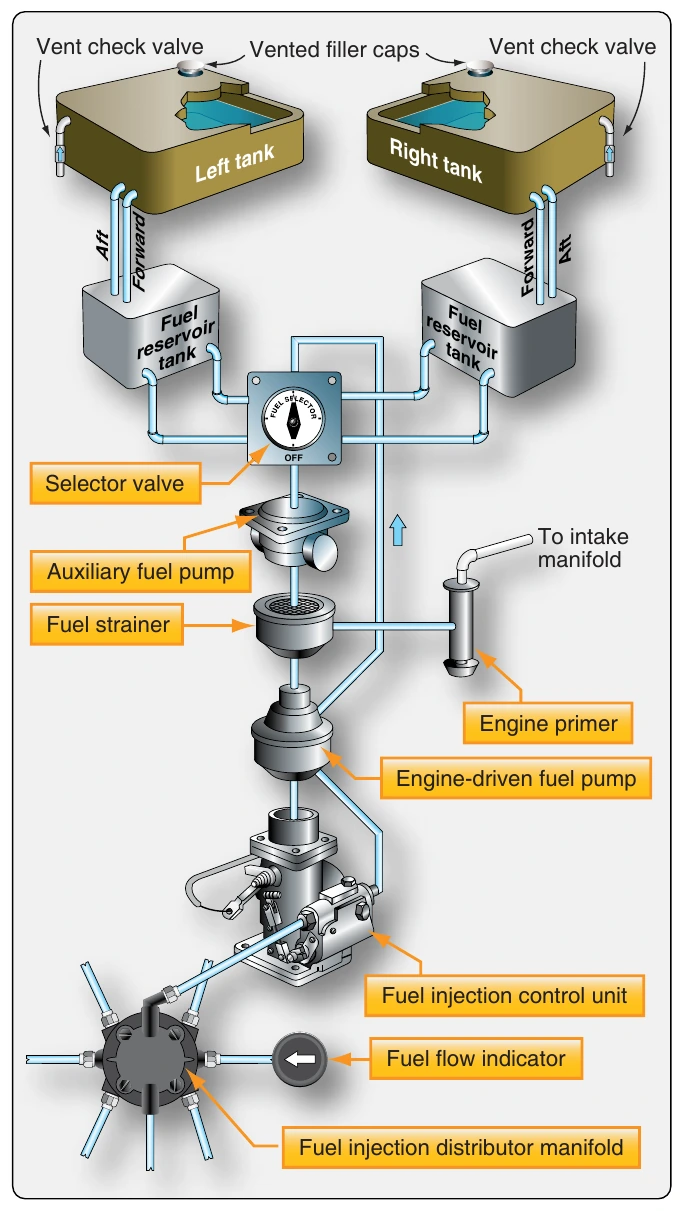
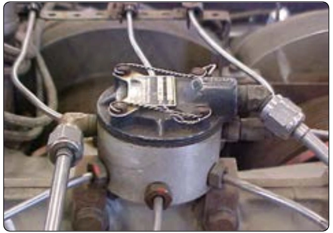
The fuel control delivers the fuel to the distribution manifold, which divides it and provides equal, consistent fuel flow for individual fuel injector in each cylinder. [Figure 14-15] A fuel flow indicator tapped off of the distribution manifold provides feedback in flight deck. It senses fuel pressure but is displayed on a dial calibrated in gallons per hour.
Small Multiengine (Reciprocating) Aircraft Fuel Systems
Low-Wing Twin
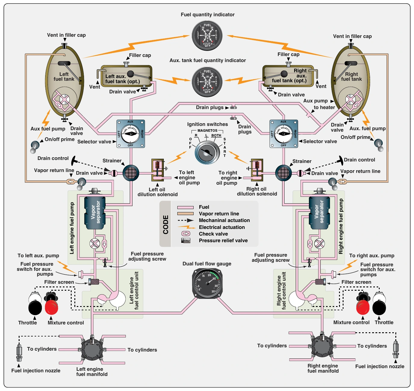
The fuel system on a small, multiengine aircraft is more complicated than a single-engine aircraft but contains many of the same elements. An example system used on a low- wing aircraft is illustrated in Figure 14-16. It features the main fuel tanks in the wing tips and auxiliary tanks in the wing structure. A boost pump is located at the outlet of each main tank. This pressurizes the entire fuel system from the tank to the injectors eliminating the possibility of vapor lock. An engine can operate with just its boost pump running in the event the engine-driven injection pump fails. Typically, the boost pumps are used to prime and start the engine.
Two selector valves are required on twin-engine aircraft, one for each engine. The right selector valve receives fuel from a main tank on either side of the aircraft and directs it to the right engine. The left selector valve also receives fuel from either main tank and directs it to the left engine. This allows fuel to crossfeed from one side of the aircraft to the opposite engine if desired. The selector valves can also direct fuel from the auxiliary tank to the engine on the same side. Crossfeed of fuel from auxiliary tanks is not possible. From the outlet of the selector valve, fuel flows to the strainer. On some aircraft, the strainer is built into the selector valve unit. From the strainer, fuel flows to the engine-driven fuel pump.
The engine-driven fuel pump is an assembly that also contains a vapor separator and a pressure regulating valve with an adjustment screw. The vapor separator helps eliminate air from the fuel. It returns a small amount of fuel and any vapor present back to the main fuel tank. The pump supplies pressurized fuel to the fuel control. The fuel control, one for each engine, responds to throttle and mixture control settings from the flight deck and supplies the proper amount of fuel to the fuel manifold. The manifold divides the fuel and sends it to an injector in each cylinder. A fuel pressure gauge is placed between the fuel control unit outlet and the manifold to monitor the injector-applied pressure that indicates engine power.