
Chapter 14
Aircraft Fuel Systems
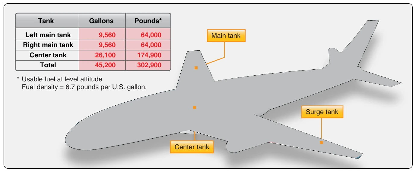
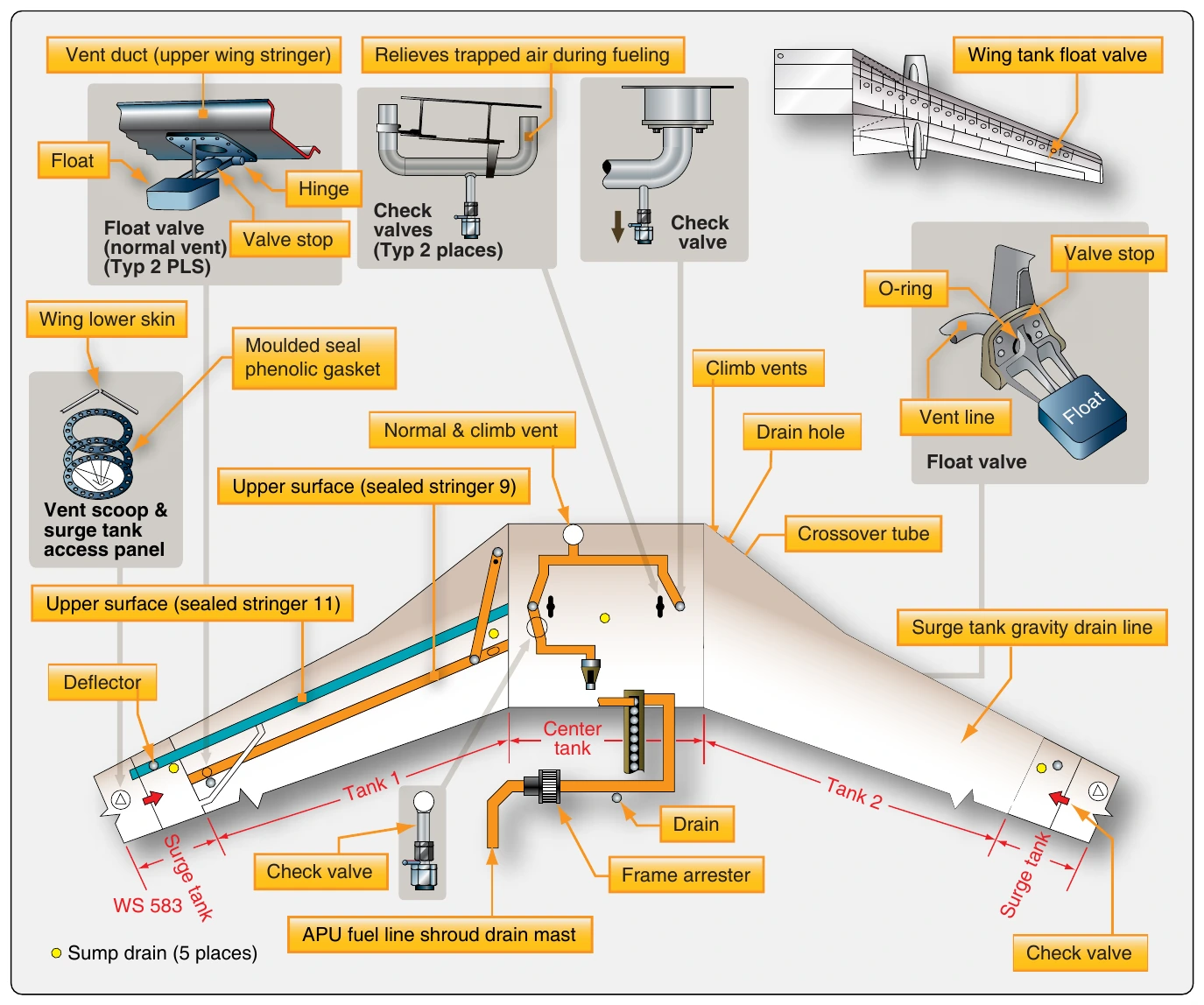
Occasionally, defueling the aircraft is required for an inspection or repair. The same fueling station is used, and the hose from the fuel truck is connected to same receptacle used to fuel the aircraft. To allow fuel to exit the aircraft, a defueling valve is opened. Fuel can either be pumped out of the aircraft using the boost pumps located in the tanks that need to be emptied, or the pump in the refueling truck can be used to draw the fuel out of the tanks. Control over the operation is maintained by positioning various shutoff and crossfeed valves, as well as the defuel valve so that fuel travels from the tank to the fueling station and into the truck.
The fuel transfer system is a series of plumbing and valves that permits movement of fuel from one tank to another on board the aircraft. In-tank fuel boost pumps move the fuel into a manifold and, by opening the fuel valve (or refueling valve) for the desired tank, the fuel is transferred. Not all jet transports have such fuel transfer capability. Through the use of a fuel feed manifold and crossfeed valves, some aircraft simply allow engines to be run off fuel from any tank as a means for managing fuel location.
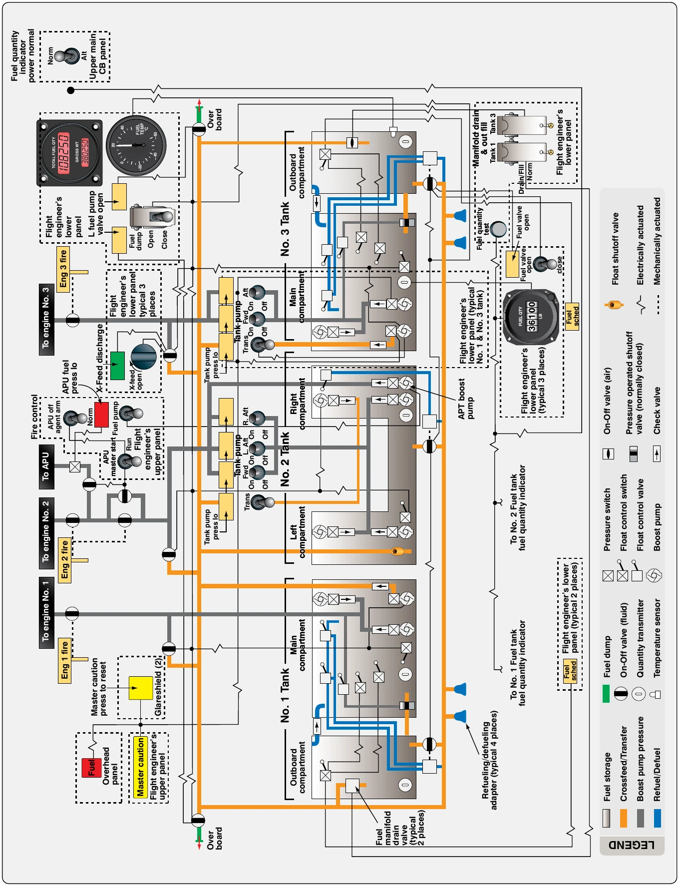
Figure 14-22 shows the fuel system diagram for a DC-10. Dedicated transfer boost pumps move fuel into a transfer manifold. Opening the fuel valve on one of the tanks transfers the fuel into that tank. The transfer manifold and boost pumps are also used to jettison fuel overboard by opening the proper dump valves with a transfer boost pump(s) operating. Additionally, the transfer system can function to supply the engines if the normal engine fuel feed malfunctions.
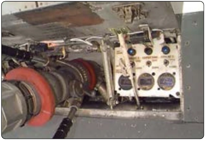
The fuel feed subsystem is sometimes considered part of the fuel distribution system. It is the heart of the fuel system since it delivers fuel to the engines. Jet transport aircraft supply fuel to the engines via in-tank fuel boost pumps, usually two per tank. They pump fuel under pressure through a shutoff valve for each engine. A manifold or connecting tubing typically allows any tank to supply any engine through the use of crossfeed valves. Boost pump bypasses allow fuel flow should a pump fail. The engines are designed to be able to run without any fuel boost pumps operating. But, each engine’s shutoff valve must be open to allow flow to the engines from the tanks.
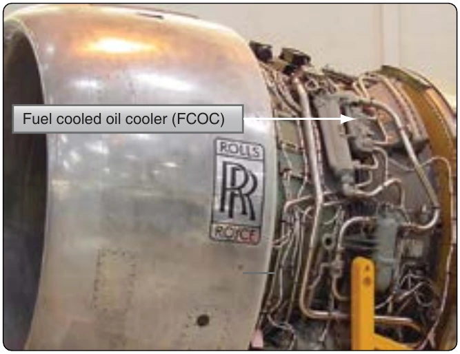
Most jet transport fuel feed systems, or the engine fuel systems, have some means for heating the fuel usually through an exchange with hot air or hot oil taken from the engine. Figure 14-23 shows the fuel cooled oil cooler (FCOC) on a Rolls Royce RB211 engine, which not only heats the fuel but also cools the engine oil.
Fuel indicating systems on jet transport aircraft monitor a variety of parameters, some not normally found on general aviation aircraft. Business jet aircraft share many of these features. True fuel flow indicators for each engine are used as the primary means for monitoring fuel delivery to the engines. A fuel temperature gauge is common as are fuel filter bypass warning lights. The temperature sensor is usually located in a main fuel tank. The indicator is located on the instrument panel or is displayed on a multifunction display (MFD). These allow the crew to monitor the fuel temperature during high altitude flight in extremely frigid conditions. The fuel filters have bypasses that permit fuel flow around the filters if clogged. Indicator light(s) illuminate in the flight deck when this occurs.
Low fuel pressure warning lights are also common on jet transport aircraft. The sensors for these are located in the boost pump outlet line. They give an indication of possible boost pump failure.
Fuel quantity gauges are important features on all aircraft. Indications exist for all tanks on a transport category aircraft. Often, these use a capacitance type fuel quantity indication system and a fuel totalizer as is discussed later in this chapter.
The location of fuel instrumentation varies depending on the type of flight deck displays utilized on the aircraft.
Helicopter Fuel Systems
Helicopter fuel systems vary. They can be simple or complex depending on the aircraft. Always consult the manufacturer’s manuals for fuel system description, operation, and maintenance instructions.
Typically, a helicopter has only one or two fuel tanks located near the center of gravity (CG) of the aircraft, which is near the main rotor mast. Thus, the tank, or tanks, are usually located in or near the aft fuselage. Some helicopter fuel tanks are mounted above the engine allowing for gravity fuel feed. Others use fuel pumps and pressure feed systems.
Fundamentally, helicopter fuel systems differ little from those on fixed-wing aircraft. Gravity-feed systems have vented fuel tanks with an outlet strainer and shutoff valve. Fuel flows from the tank through a main filter to the carburetor. [Figure 14-24]
A slightly more complex system for a light turbine-powered helicopter is shown in Figure 14-25. Two in-tank electric boost pumps send fuel through a shutoff valve rather than a selector valve, since there is only one fuel tank. It flows through an airframe filter to an engine filter and then to the engine-driven fuel pump. The fuel tank is vented and contains an electrically operated sump drain valve. A pressure gauge is used to monitor boost pump output pressure and differential pressure switches warn of fuel filter restrictions. Fuel quantity is derived through the use of two in-tank fuel probes with transmitters.
Larger, heavy, multiengine transport helicopters have complex fuel systems similar to jet transport fixed-wing aircraft. They may feature multiple fuel tanks, crossfeed systems, and pressure refueling.