
Chapter 14
Aircraft Fuel Systems
High-Wing Twin
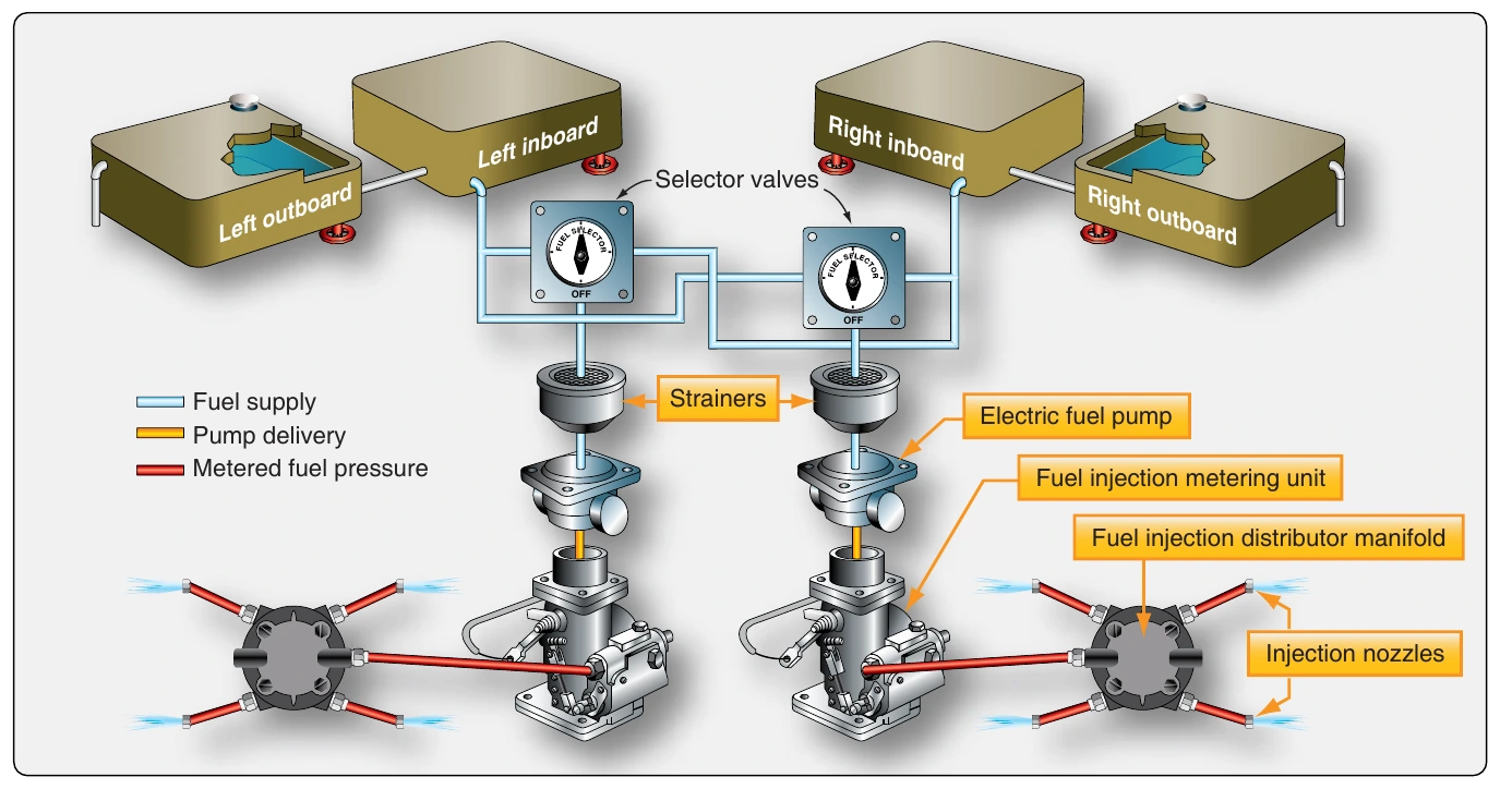
A simplified system on a high-wing, twin-engine aircraft that combines gravity feed with an electric fuel pump is illustrated in Figure 14-17. Directly downstream of the selector valves are the fuel strainers and then an electric fuel pump for each engine. This pump draws fuel from the selected tank and sends it under pressure to the inlet side of the fuel injection metering unit. The metering unit for each engine provides the proper flow of fuel to the distribution manifold which feeds the injectors.
Large Reciprocating-Engine Aircraft Fuel Systems
Large, multiengine transport aircraft powered by reciprocating radial engines are no longer produced. However, many are still in operation. They are mostly carbureted and share many features with the light aircraft systems previously discussed.
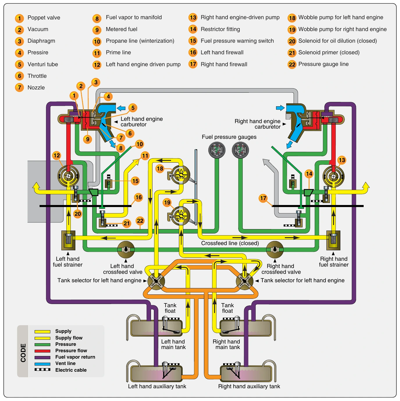
Figure 14-18 shows the fuel system of a DC-3. A selector valve for each engine allows an engine-driven pump to pull fuel from the main tank or an auxiliary tank. The fuel passes through a strainer before reaching the pump where it is delivered to the engine. The outlet of the pump can feed either engine through the use of a crossfeed line with valves controlled in the flight deck. A hand-operated wobble pump located upstream of the strainer is used to prime the system for starting. Fuel vapor lines run from the pressure carburetor to the vent space in the main and auxiliary tanks. Fuel pressure gauges are tapped off of the carburetor for power indication.
The hand-operated wobble pumps were replaced by electric pumps on later model aircraft. A fuel pressure warning light tapped in downstream of the engine-driven fuel pump alerts the crew should fuel pressure decline.
Not all large, old aircraft have this fuel system. This is merely an example. Other aircraft share similar features and possess unique features of their own. The same is true for small reciprocating-engine aircraft. There are many systems that share features with those described above, but they also differ in some ways. Always consult the manufacturer’s data when working on aircraft fuel systems and follow all instructions for service and repair. The fuel system of an aircraft provides the life blood for engine operation and must be maintained with the highest discretion.
Jet Transport Aircraft Fuel Systems
Fuel systems on large transport category jet aircraft are complex with some features and components not found in reciprocating-engine aircraft fuel systems. They typically contain more redundancy and facilitate numerous options from which the crew can choose while managing the aircraft’s fuel load. Features like an onboard APU, single point pressure refueling, and fuel jettison systems, which are not needed on smaller aircraft, add to the complexity of an airliner fuel system.
Jet transport fuel systems can be regarded as a handful of fuel subsystems as follows:
- Storage.
- Vent.
- Distribution.
- Feed.
- Indicating.
Most transport category aircraft fuel systems are very much alike. Integral fuel tanks are the norm with much of each wing’s structure sealed to enable its use as a fuel tank. Center wing section or fuselage tanks are also common. These may be sealed structure or bladder type. Jet transport aircraft carry tens of thousands of pounds of fuel on board. Figure 14-19 shows a diagram of a Boeing 777 fuel tank configuration with tank capacities.
There are optional fuel storage configurations available on the same model airliner. For example, airlines expecting to use an aircraft on transoceanic flights may order the aircraft with long-range auxiliary tanks. These additional tanks, usually located in the fuselage section of the aircraft, can alter fuel management logistics in addition to complicating the fuel system.
In addition to main and auxiliary fuel tanks, surge tanks may also be found on jet transports. These normally empty tanks located in the wing structure outboard of the main wing tanks are used for fuel overflow. A check valve allows the one-way drainage of fuel back into the main tanks. Surge tanks are also used for fuel system venting.
Transport category fuel systems require venting similar to reciprocating engine aircraft fuel systems. A series of vent tubing and channels exists that connects all tanks to vent space in the surge tanks (if present) or vent overboard. Venting must be configured to ensure the fuel is vented regardless of the attitude of the aircraft or the quantity of fuel on board. This sometimes requires the installation of various check valves, float valves, and multiple vent locations in the same tank. Figure 14-20 shows the fuel vent system of a Boeing 737.
A transport category aircraft fuel distribution subsystem consists of the pressure fueling components, defueling components, transfer system, and fuel jettison or dump system. Single-point pressure fueling at a fueling station accessible by ramp refueling trucks allows all aircraft fuel tanks to be filled with one connection of the fuel hose. Leading and trailing edge wing locations are common for these stations. Figure 14-21 shows an airliner fueling station with the fueling rig attached.
To fuel with pressure refueling, a hose nozzle is attached at the fueling station and valves to the tanks required to be filled are opened. These valves are called fueling valves or refueling valves depending upon the manufacturer’s preference. Various automatic shutoff systems have been designed to close tank fueling valves before the tanks overfill or are damaged. Gauges on the refueling panel allow refueling personnel to monitor progress.