
Chapter 4
Aircraft Metal Structural Repair
Typically, rivets are fabricated from aluminum alloys, such as 2017-T4, 2024-T4, 2117-T4, 7050, and 5056. Titanium, nickel-based alloys, such as Monel® (corrosion-resistant steel), mild steel or iron, and copper rivets are also used for rivets in certain cases.
Rivets are available in a wide variety of alloys, head shapes, and sizes and have a wide variety of uses in aircraft structure. Rivets that are satisfactory for one part of the aircraft are often unsatisfactory for another part. Therefore, it is important that an aircraft technician know the strength and driving properties of the various types of rivets and how to identify them, as well as how to drive or install them.
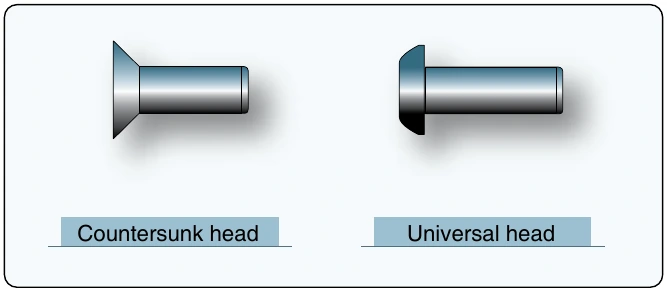
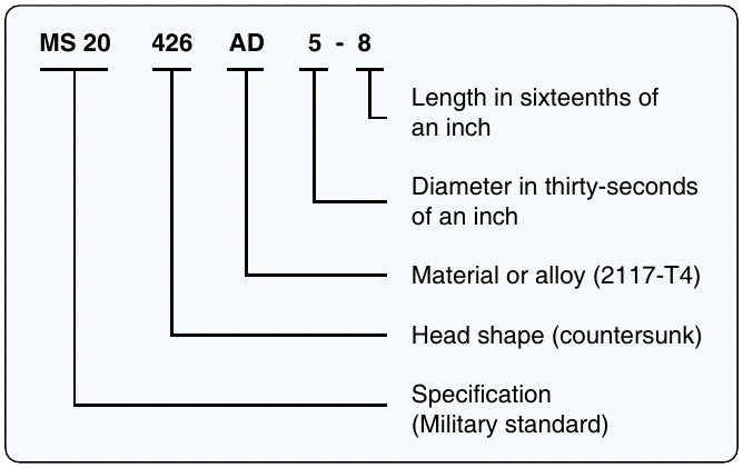
Solid rivets are classified by their head shape, by the material from which they are manufactured, and by their size. Identification codes used are derived from a combination of the Military Standard (MS) and National Aerospace Standard (NAS) systems, as well as an older classification system known as AN for Army/Navy. For example, the prefix MS identifies hardware that conforms to written military standards. A letter or letters following the head-shaped code identify the material or alloy from which the rivet was made. The alloy code is followed by two numbers separated by a dash. The first number is the numerator of a fraction, which specifies the shank diameter in thirty-seconds of an inch. The second number is the numerator of a fraction in sixteenths of an inch and identifies the length of the rivet. Rivet head shapes and their identifying code numbers are shown in Figure 4-75.
The most frequently used repair rivet is the AD rivet because it can be installed in the received condition. Some rivet alloys, such as DD rivets (alloy 2024-T4), are too hard to drive in the received condition and must be annealed before they can be installed. Typically, these rivets are annealed and stored in a freezer to retard hardening, which has led to the nickname “ice box rivets.” They are removed from the freezer just prior to use. Most DD rivets have been replaced by E-type rivets which can be installed in the received condition.
The head type, size, and strength required in a rivet are governed by such factors as the kind of forces present at the point riveted, the kind and thickness of the material to be riveted, and the location of the part on the aircraft. The type of head needed for a particular job is determined by where it is to be installed. Countersunk head rivets should be used where a smooth aerodynamic surface is required. Universal head rivets may be used in most other areas.
The size (or diameter) of the selected rivet shank should correspond in general to the thickness of the material being riveted. If an excessively large rivet is used in a thin material, the force necessary to drive the rivet properly causes an undesirable bulging around the rivet head. On the other hand, if an excessively small rivet diameter is selected for thick material, the shear strength of the rivet is not great enough to carry the load of the joint. As a general rule, the rivet diameter should be at least two and a half to three times the thickness of the thicker sheet. Rivets most commonly chosen in the assembly and repair of aircraft range from 3⁄32-inch to 3⁄8-inch in diameter. Ordinarily, rivets smaller than 3⁄32-inch in diameter are never used on any structural parts that carry stresses.
The proper sized rivets to use for any repair can also be determined by referring to the rivets (used by the manufacturer) in the next parallel row inboard on the wing or forward on the fuselage. Another method of determining the size of rivets to be used is to multiply the skin’s thickness by 3 and use the next larger size rivet corresponding to that figure. For example, if the skin is 0.040 inch thick, multiply 0.040 inch by 3 to get 0.120 inch and use the next larger size of rivet, 1⁄8-inch (0.125 inch).
When rivets are to pass completely through tubular members, select a rivet diameter equivalent to at least 1⁄8 the outside diameter of the tube. If one tube sleeves or fits over another, take the outside diameter of the outside tube and use one-eighth of that distance as the minimum rivet diameter. A good practice is to calculate the minimum rivet diameter and then use the next larger size rivet.
Whenever possible, select rivets of the same alloy number as the material being riveted. For example, use 1100 and 3003 rivets on parts fabricated from 1100 and 3003 alloys, and 2117-1 and 2017-T rivets on parts fabricated from 2017 and 2024 alloys.
The size of the formed head is the visual standard of a proper rivet installation. The minimum and maximum sizes, as well as the ideal size, are shown in Figure 4-76.
Installation of Rivets
Repair Layout
Repair layout involves determining the number of rivets required, the proper size and style of rivets to be used, their material, temper condition and strength, the size of the holes, the distances between the holes, and the distance between the holes and the edges of the patch. Distances are measured in terms of rivet diameter.
Rivet Length
To determine the total length of a rivet to be installed, the combined thickness of the materials to be joined must first be known. This measurement is known as the grip length. The total length of the rivet equals the grip length plus the amount of rivet shank needed to form a proper shop head.
The properly formed shop head equals one and a half times the diameter of the rivet shank. Where A is total rivet length, B is grip length, and C is the length of the material needed