
Chapter 4
Aircraft Metal Structural Repair
The file is an important but often overlooked tool used to shape metal by cutting and abrasion. Files have five distinct properties: length, contour, the form in cross section, the kind of teeth, and the fineness of the teeth. Many different types of files are available and the sizes range from 3 to 18 inches. [Figure 4-36]
The portion of the file on which the teeth are cut is called the face. The tapered end that fits into the handle is called the tang. The part of the file where the tang begins is the heel. The length of a file is the distance from the point or tip to the heel and does not include the tang. The teeth of the file do the cutting. These teeth are set at an angle across the face of the file. A file with a single row of parallel teeth is called a single-cut file. The teeth are cut at an angle of 65°–85° to the centerline, depending on the intended use of the file. Files that have one row of teeth crossing another row in a crisscross pattern are called double-cut files. The angle of the first set usually is 40°–50° and that of the crossing teeth 70°–80°. Crisscrossing produces a surface that has a very large number of little teeth that slant toward the tip of the file. Each little tooth looks like an end of a diamond point cold chisel.
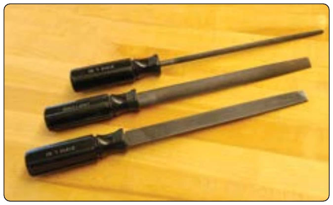
Files are graded according to the tooth spacing; a coarse file has a small number of large teeth, and a smooth file has a large number of fine teeth. The coarser the teeth, the more metal is removed on each stroke of the file. The terms used to indicate the coarseness or fineness of a file are rough, coarse, bastard, second cut, smooth, and dead smooth, and the file may be either single cut or double cut. Files are further classified according to their shape. Some of the more common types are: flat, triangle, square, half round, and round.
There are several filing techniques. The most common is to remove rough edges and slivers from the finished part before it is installed. Crossfiling is a method used for filing the edges of metal parts that must fit tightly together. Crossfiling involves clamping the metal between two strips of wood and filing the edge of the metal down to a preset line. Draw filing is used when larger surfaces need to be smoothed and squared. It is done by drawing the file over the entire surface of the work.
To protect the teeth of a file, files should be stored separately in a plastic wrap or hung by their handles. Files kept in a toolbox should be wrapped in waxed paper to prevent rust from forming on the teeth. File teeth can be cleaned with a file card.
Die Grinder
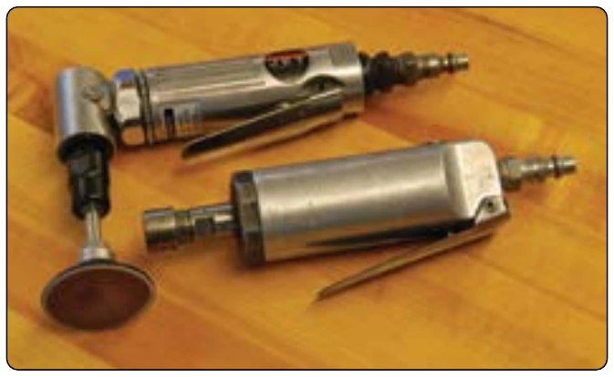
A die grinder is a handheld tool that turns a mounted cutoff wheel, rotary file, or sanding disc at high speed. [Figure 4-37] Usually powered by compressed air, electric die grinders are also used. Pneumatic die grinders run at 12,000 to 20,000 revolutions per minute (rpm) with the rotational speed controlled by the operator who uses a hand-or foot-operated throttle to vary the volume of compressed air. Available in straight, 45°, and 90° models, the die grinder is excellent for weld breaking, smoothing sharp edges, deburring, porting, and general high-speed polishing, grinding, and cutting.
Burring Tool
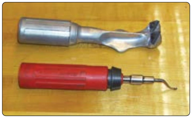
This type of tool is used to remove a burr from an edge of a sheet or to deburr a hole. [Figure 4-38]
Hole Drilling
Drilling holes is a common operation in the airframe repair shop. Once the fundamentals of drills and their uses are learned, drilling holes for rivets and bolts on light metal is not difficult. While a small portable power drill is usually the most practical tool for this common operation in airframe metalwork, sometimes a drill press may prove to be the better piece of equipment for the job.
Portable Power Drills
Portable power drills operate by electricity or compressed air. Pneumatic drill motors are recommended for use on repairs around flammable materials where potential sparks from an electric drill motor might become a fire hazard.
When using the portable power drill, hold it firmly with both hands. Before drilling, be sure to place a backup block of wood under the hole to be drilled to add support to the metal structure. The drill bit should be inserted in the chuck and tested for trueness or vibration. This may be visibly checked by running the motor freely. A drill bit that wobbles or is slightly bent should not be used since such a condition causes enlarged holes. The drill should always be held at right angles to the work regardless of the position or curvatures. Tilting the drill at any time when drilling into or withdrawing from the material may cause elongation (egg shape) of the hole. When drilling through sheet metal, small burrs are formed around the edge of the hole. Burrs must be removed to allow rivets or bolts to fit snugly and to prevent scratching. Burrs may be removed with a bearing scraper, a countersink, or a drill bit larger than the hole. If a drill bit or countersink is used, it should be rotated by hand. Always wear safety goggles while drilling.
Pneumatic Drill Motors
Pneumatic drill motors are the most common type of drill motor for aircraft repair work. [Figure 4-39] They are lightweight and have sufficient power and good speed control. Drill motors are available in many different sizes and models. Most drill motors used for aircraft sheet metal work are rated at 3,000 rpm, but if drilling deep holes or drilling in hard materials, such as corrosion resistant steel or titanium, a drill motor with more torque and lower rpm should be selected to prevent damage to tools and materials.