Chapter 4
Engine Ignition & Electrical Systems
Spark Plug Lead Installation
Before installing the spark plug lead, carefully wipe the terminal sleeve and the integral seal with a cloth moistened with acetone or an approved solvent. After the plug lead is cleaned, inspect it for cracks and scratches. If the terminal sleeve is damaged or heavily stained, replace it.
Application of a light coating of an insulating material to the outer surface of the terminal sleeve, as well as filling the space occupied by the contact spring, is sometimes recommended. By occupying the space in the electrical contact area of the shielding barrel, the insulating material prevents moisture from entering the contact area and shorting the spark plug.
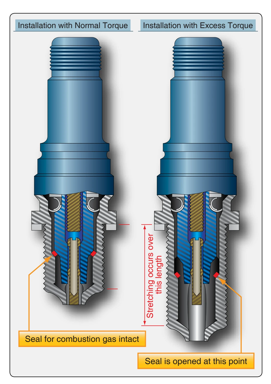
Some manufacturers recommend the use of such insulating compounds only when moisture in the ignition system becomes a problem, and others have discontinued the use of such materials.
After inspection of the spark plug lead, slip the lead into the shielding barrel of the plug with care. Then, tighten the spark plug coupling elbow nut with the proper tool. Most manufacturers’ instructions specify the use of a tool designed to help prevent an overtorque condition. After the coupling nut is tightened, avoid checking for tightness by twisting the body of the elbow.
After all plugs have been installed, torqued, and the leads properly installed, start the engine and perform a complete ignition system operational check.
Breaker Point Inspection
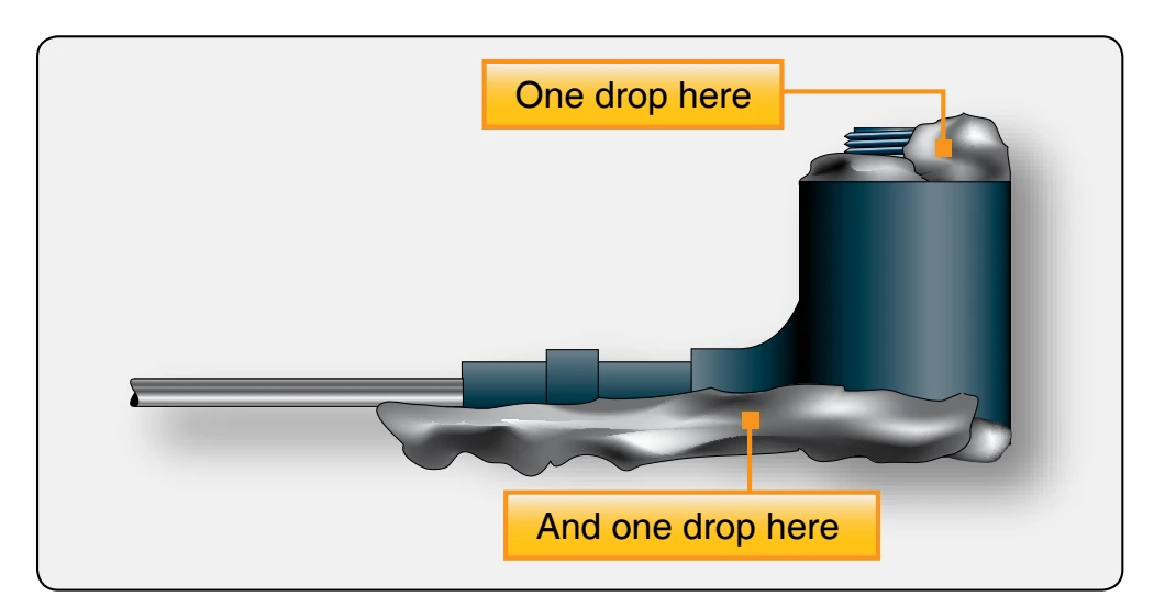
Inspection of the magneto consists essentially of a periodic breaker point and dielectric inspection. After the magneto has been inspected for security of mounting, remove the magneto cover, or breaker cover, and check the cam for proper lubrication. Under normal conditions, there is usually ample oil in the felt oiler pad of the cam follower to keep the cam lubricated between overhaul periods. However, during the regular routine inspection, examine the felt pad on the cam follower to be sure it contains sufficient oil for cam lubrication. Make this check by pressing the thumbnail against the oiler pad. If oil appears on the thumbnail, the pad contains sufficient oil for cam lubrication. If there is no evidence of oil on the fingernail, apply one drop of a light aircraft engine oil to the bottom felt pad and one drop to the upper felt pad of the follower assembly. [Figure 4-65]
After application, allow at least 15 minutes for the felt to absorb the oil. At the end of 15 minutes, blot off any excess oil with a clean, lint-free cloth. During this operation, or any time the magneto cover is off, use extreme care to keep the breaker compartment free of oil, grease, or engine cleaning solvents, since each of these have an adhesiveness that collects dirt and grime that could foul an otherwise good set of breaker contact points.
After the felt oiler pad has been inspected, serviced, and found to be satisfactory, visually inspect the breaker contacts for any condition that may interfere with proper operation of the magneto. If the inspection reveals an oily or gummy substance on the sides of the contacts, swab the contacts with a flexible wiper, such as a pipe cleaner dipped in acetone or other approved solvent. By forming a hook on the end of the wiper, ready access can be gained to the back side of the contacts.
To clean the contact mating surfaces, force open the breaker points enough to admit a small swab. Whether spreading the points for purposes of cleaning or checking the surfaces for condition, always apply the opening force at the outer end of the mainspring and never spread the contacts more than 1⁄16 inch. If the contacts are spread wider than recommended, the mainspring, the spring carrying the movable contact point, is likely to take a permanent set. If the mainspring takes a permanent set, the movable contact point loses some of its closing tension and the points then either bounce or float, preventing the normal induction buildup of the magneto.
A swab can be made by wrapping a piece of linen tape or a small piece of lint-free cloth over one of the leaves of a clearance gauge and dipping the swab in an approved solvent. Pass the swab between the carefully separated contact surfaces until the surfaces are clean. During this entire operation, take care that drops of solvent do not fall on lubricated parts, such as the cam, follower block, or felt oiler pad.
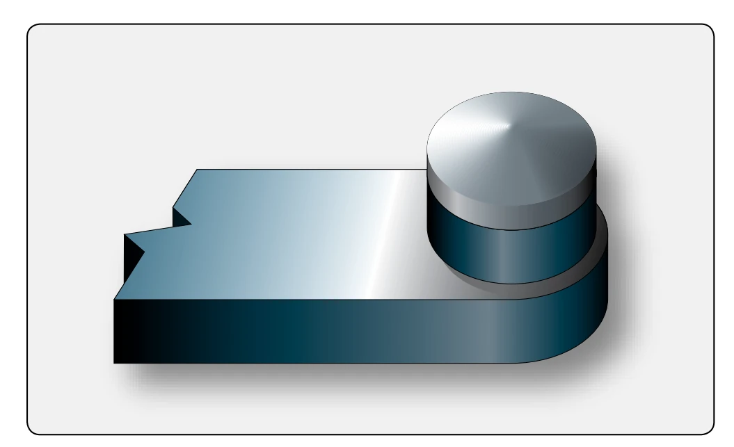
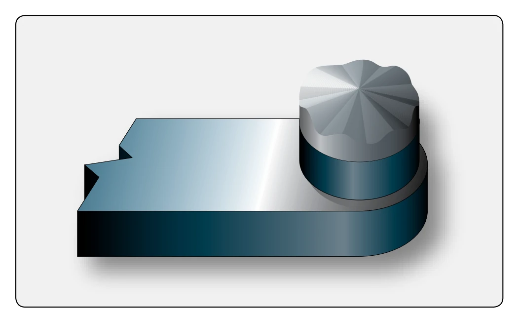
To inspect the breaker contact surfaces, it is necessary to know what a normal operating set of contacts looks like, what surface condition is considered as permissible wear, and what surface condition is cause for dressing or replacement. The probable cause of an abnormal surface condition can be determined from the contact appearance. The normal contact surface has a dull gray, sandblasted, almost rough appearance over the area where electrical contact is made. [Figure 4-66] This gray, sandblasted appearance indicates that the points have worn in and have mated to each other and are providing the best possible electrical contact. This does not imply that this is the only acceptable contact surface condition. Slight, smooth-surfaced irregularities, without deep pits or high peaks, such as shown in Figure 4-67, are considered normal wear and are not cause for replacement.
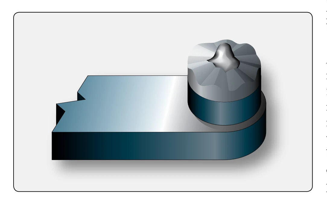
However, when wear advances to a point where the slight, smooth irregularities develop into well-defined peaks extending noticeably above the surrounding surface, the breaker contacts must be replaced. [Figure 4-68]
Unfortunately, when a peak forms on one contact, the mating