
Chapter 4
Engine Ignition & Electrical Systems
contact has a corresponding pit or hole. This pit is more troublesome than the peak because it penetrates the platinum pad of the contact surface. It is sometimes difficult to judge whether a contact surface is pitted deeply enough to require replacement because this depends on how much of the original platinum is left on the contact surface. The danger arises from the possibility that the platinum pad may already be thin as a result of long service life and previous dressings. At overhaul facilities, a gauge is used to measure the remaining thickness of the pad, and no difficulty in determining the condition of the pad exists. But at line maintenance activities, this gauge is generally unavailable.
Therefore, if the peak is quite high or the pit quite deep, remove and replace them with a new assembly. A comparison between Figures 4-67 and 4-68 will help to draw the line between minor irregularities and well-defined peaks.
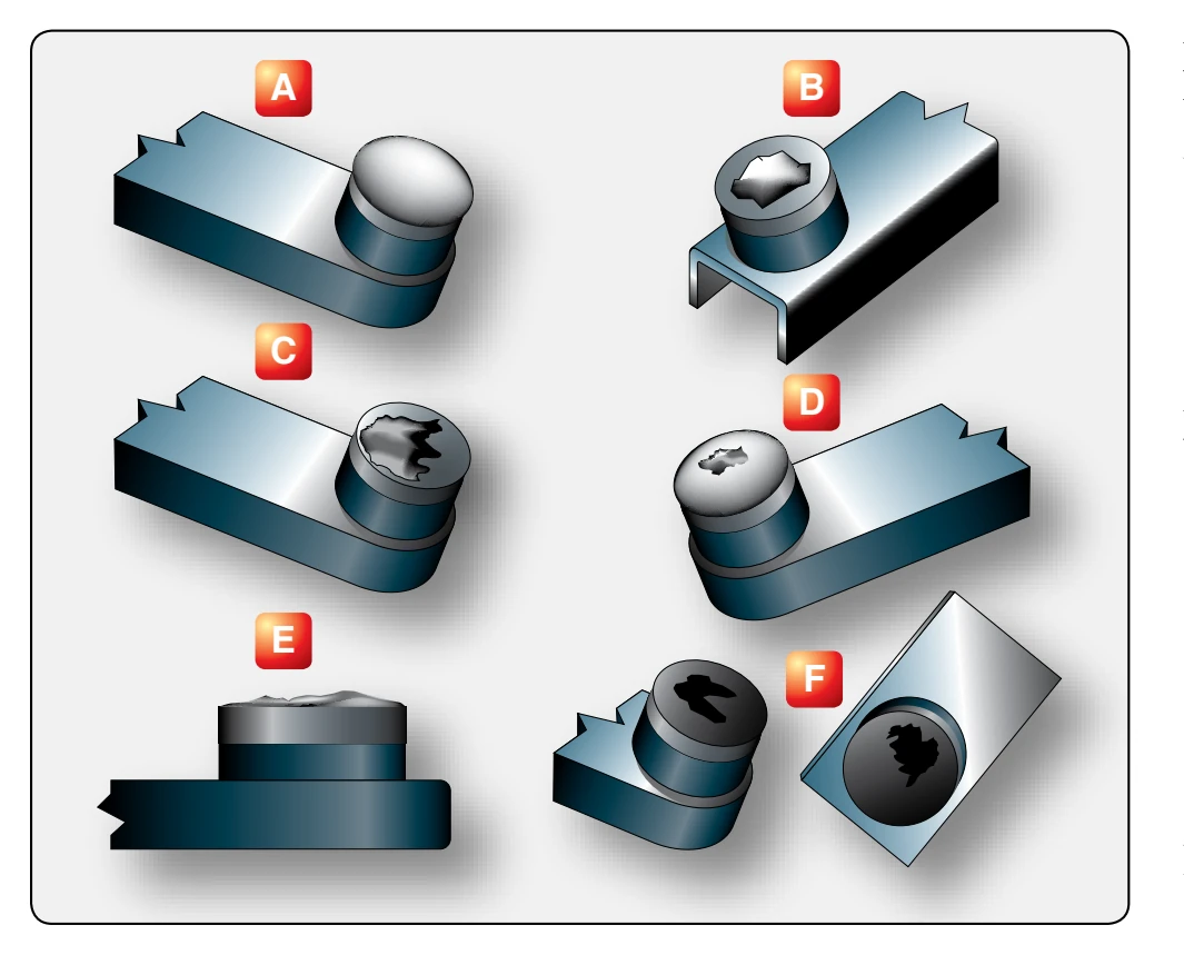
Some examples of possible breaker contact surface conditions are illustrated in Figure 4-69. Item A illustrates an example of erosion or wear called frosting. This condition results from an open-circuited condenser and is easily recognized by the coarse, crystalline surface and the black “sooty” appearance of the sides of the points. The lack of effective condenser action results in an arc of intense heat being formed each time the points open. This, together with the oxygen in the air, rapidly oxidizes and erodes the platinum surface of the points, producing the coarse, crystalline, or frosted appearance. Properly operating points have a fine-grained, frosted, or silvery appearance and should not be confused with the coarsegrained and sooty point caused by faulty condenser action.
Figure 4-69B and C illustrate badly pitted points. In the early stage, these points are identified by a fairly even contact edge and minute pits or pocks in or near the center of the contact surface with an overall smoky appearance. In more advanced stages, the pit may develop into a large, jagged crater, and eventually the entire contact surface takes on a burned, black, and crumpled appearance. Pitted points, as a general rule, are caused by dirt and impurities on the contact surfaces. If points are excessively pitted, a new breaker assembly must be installed.
Figure 4-69E illustrates a built-up point that can be recognized by the mound of metal that has been transferred from one point to another. Buildup, like the other conditions mentioned, results primarily from the transfer of contact material by means of the arc as the points separate. But, unlike the others, there is no burning or oxidation in the process because of the closeness of the pit of one point and the buildup of the other. This condition may result from excessive breaker point spring tension that retards the opening of the points or causes a slow, lazy break. It can also be caused by a poor primary condenser or a loose connection at the primary coil. If excessive buildup has occurred, a new breaker assembly must be installed.
Figure 4-69F illustrates oily points that can be recognized by their smoked and smudged appearance and by the lack of any of the previously mentioned irregularities. This condition may be the result of excessive cam lubrication or of oil vapors that may come from within or outside the magneto. A smoking or fuming engine, for example, could produce the oil vapors. These vapors then enter the magneto through the magneto ventilator and pass between and around the points. These conductive vapors produce arcing and burning on the
contact surfaces. The vapors also adhere to the other surfaces of the breaker assembly and form the sooty deposit. If so, install new breaker assembly.
Dielectric Inspection
Another phase of magneto inspection is the dielectric inspection. This inspection is a visual check for cleanliness and cracks. If inspection reveals that the coil cases, condensers, distributor rotor, or blocks are oily or dirty or have any trace of carbon tracking, they require cleaning and possibly waxing to restore their dielectric qualities.
Clean all accessible condensers and coil cases that contain condensers by wiping them with a lint-free cloth moistened with acetone. Many parts of this type have a protective coating. This protective coating is not affected by acetone, but it may be damaged by scraping or by the use of other cleaning fluids. Never use unapproved cleaning solvents or improper cleaning methods. Also, when cleaning condensers or parts that contain condensers, do not dip, submerge, or saturate the parts in any solution because the solution used may seep inside the condenser and short out the plates.
Coil cases, distributor blocks, distributor rotors, and other dielectric parts of the ignition system are treated with a wax coating when they are new and again at overhaul. The waxing of dielectrics aids their resistance to moisture absorption, carbon tracking, and acid deposits. When these parts become dirty or oily, some of the original protection is lost, and carbon tracking may result.
If any hairline carbon tracks or acid deposits are present on the surface of the dielectric, immerse the part in approved cleaning solvent and scrub it vigorously with a stiff bristle brush. When the carbon track or acid deposits have been removed, wipe the part with a clean, dry cloth to remove all traces of the solvent used for cleaning. Then, coat the part with a special ignitiontreating wax. After wax treating the part, remove excess wax deposits and reinstall the part in the magneto.
Ignition Harness Maintenance
Although the ignition harness is simple, it is a vital link between the magneto and spark plug. Because the harness is mounted on the engine and exposed to the atmosphere, it is vulnerable to heat, moisture, and the effects of changing altitude. These factors, plus aging insulation and normal gap erosion, work against efficient engine operation. The insulation may break down on a wire inside the harness and allow the high-voltage to leak through the insulation to the harness shielding instead of going to the spark plug. Open circuits may result from broken wires or poor connections. A bare wire may be in physical contact with the shielding, or two wires may be shorted together.
Any serious defect in an individual lead prevents the hightension impulse from reaching the spark plug to which the lead is connected. As a result, this plug will not fire. When only one spark plug is firing in a cylinder, the charge is not consumed as quickly as it would be if both plugs were firing. This factor causes the peak pressure of combustion to occur later on in the power stroke. If the peak pressure in the cylinder occurs later, a loss of power in that cylinder results. However, the power loss from a single cylinder becomes a minor factor when the effects of a longer burning time is considered. A longer burning time overheats the affected cylinder, causing detonation, possible pre-ignition, and perhaps permanent damage to the cylinder.
High-Tension Ignition Harness Faults
Perhaps the most common and most difficult high-tension ignition system faults to detect are high-voltage leaks. This is leakage from the core conductor through insulation to the ground of the shielded manifold. A certain small amount of leakage exists even in brand new ignition cable during normal operation. Various factors combine to produce first a high rate of leakage and then complete breakdown. Of these factors, moisture in any form is probably the worst.
Under high-voltage stress, an arc forms and burns a path across the insulator where the moisture exists. If there is gasoline, oil, or grease present, it breaks down and forms carbon. The burned path is called a carbon track, since it is actually a path of carbon particles. With some types of insulation, it may be possible to remove the carbon track and restore the insulator to its former useful condition. This is generally true of porcelain, ceramics, and some of the plastics because these materials are not hydrocarbons and any carbon track forming on them is the result of a dirt film that can be wiped away.
Differences in location and amount of leakage produce different indications of malfunction during engine operation. Indications are generally misfiring or crossfiring. The indication may be intermittent, changing with manifold pressure or with climate conditions. An increase in manifold pressure increases the compression pressure and the resistance of the air across the air gap of the spark plugs. An increase in the resistance at the air gap opposes the spark discharge and produces a tendency for the spark to discharge at some weak point in the insulation. A weak spot in the harness may be aggravated by moisture collecting in the harness manifold. With moisture present, continued engine operation causes the intermittent faults to become permanent carbon tracks. Thus, the first indication of ignition harness unserviceability may be engine misfiring or roughness caused by partial leakage of the ignition voltage.