
Chapter 8
Engine Removal & Replacement
Check the outer surface of all exposed electrical wiring for breaks, chafing, or other damage. Also, check the security of crimped or soldered cable ends. In addition, carefully inspect connector plugs for overall condition. Any item that is damaged must be repaired or replaced, depending on the extent of the damage.
Before installing an engine, inspect all tubing in the nacelle for dents, nicks, scratches, chafing, or corrosion. Check all tubing carefully for indications of fatigue or excessive flatness caused by improper or accidental bending. Thoroughly inspect all hoses used in various engine systems. Weather checking (a cracking of the outside covering of the hose) sometimes penetrates to the hose reinforcement. Replace any length of hose that shows indications of the cover peeling or flaking or has exposed fabric reinforcement. Replace a hose that shows indications of excessive cold flow. Cold flow is a term used to describe the deep and permanent impressions or cracks caused by hose clamp pressure.
Always replace a control rod if it is nicked or corroded deeply enough to affect its strength. If the corrosion cannot be removed by rubbing with steel wool, the pitting is too deep for safety.
On older aircraft, check the pulleys in the control system for freedom of movement. It is easy to spot a pulley that is not turning freely, for both it and the cable are worn from the cable sliding over the pulley instead of rolling free. The bearings of a pulley may be checked by inspecting the pulley for excessive play or wobble with the tension removed from the cable. The cable must also be inspected for corrosion and broken strands. Locate any broken strands by wiping the cable with a cloth.
Check bonding for fraying, loose attachment, and cleanness of terminal ends. The electrical resistance of the complete bond must not exceed the resistance values specified in the applicable manufacturer’s instructions.
Inspect the exhaust stacks, collector ring, and tailpipe assembly for security, cracks, or excessive corrosion. Depending on the installation, these units, or parts of them, may be mounted on the engine before it is installed in the aircraft.
Check all air ducts for dents and for the condition of the fabric or rubber anti-chafing strips at the points where sections of duct are joined. The dents may be pounded out; the anti-chafing strips should be replaced if they are pulled loose from the duct or are worn to the point at which they no longer form a tight seal at the joint.
Thoroughly inspect the engine oil system and perform any required special maintenance upon it before installing a replacement engine. If an engine is being changed at the end of its normal time in service, it is usually necessary only to flush the oil system; however, if an engine has been removed for internal failure, usually some units of the oil system must be replaced and others thoroughly cleaned and inspected.
If the engine has been removed because of internal failure, the oil tank is generally removed to permit thorough cleaning. Also, the oil cooler and temperature regulator must be removed and sent to a repair facility for overhaul. The vacuum pump pressure line and the oil separator in the vacuum system must also be removed, cleaned, and inspected. Internal failure also requires that the propeller governor and feathering pump mechanism be replaced if these units are operated by engine oil pressure.
Preparing the Engine for Removal
Before starting to work on the aircraft or reciprocating engine, always be sure that the magneto switch is in the off position. Aircraft engines can be started accidentally by turning the propeller if the magneto switch is on.
Check to see that all fuel selectors or solenoid-operated fuel shutoff valves are closed. The fuel selector valves are either manually or solenoid operated. If solenoid-operated fuel shutoff valves are installed, it may be necessary to turn the battery switch on before the valves can be closed, since the solenoid depends on electricity for operation. These valves close the fuel line at the firewall between the engine and the aircraft. After ensuring that all fuel to the engine is shut off, disconnect the battery to eliminate the possibility of a hot wire starting a fire. If it is anticipated that the aircraft will be out of service for more than 6 days, the battery is usually removed and taken to the battery shop and placed on charge.
Also, a few other preparations should be made before starting to work on the engine removal. First, make sure that there are enough fire extinguishers near at hand to meet any possible emergency. Check the seals on these extinguishers to be sure the extinguishers have not been discharged. Then, check the wheel chocks. If these are not in place, the aircraft can, and probably will, inch forward or back during some crucial operation. Also, if the aircraft has a tricycle landing gear, be sure that the tail is supported so that the aircraft cannot tip back when the weight of the engine is removed from the forward end. It is not necessary to support the tail on some multiengine aircraft if only one engine is to be removed. In addition, the landing gear shock struts can be deflated to prevent them from extending as the engine weight is removed from the aircraft.
After taking these necessary precautions, begin removing the cowling from around the engine. As it is removed, clean it and check for cracks so that the necessary repairs can be made while the engine change is in progress. Place all cowling that does not need repair on a rack where it can be readily found when the time comes to reinstall it on the new engine. After removing the cowling, the propeller should be removed for inspection or repair.
Draining the Engine
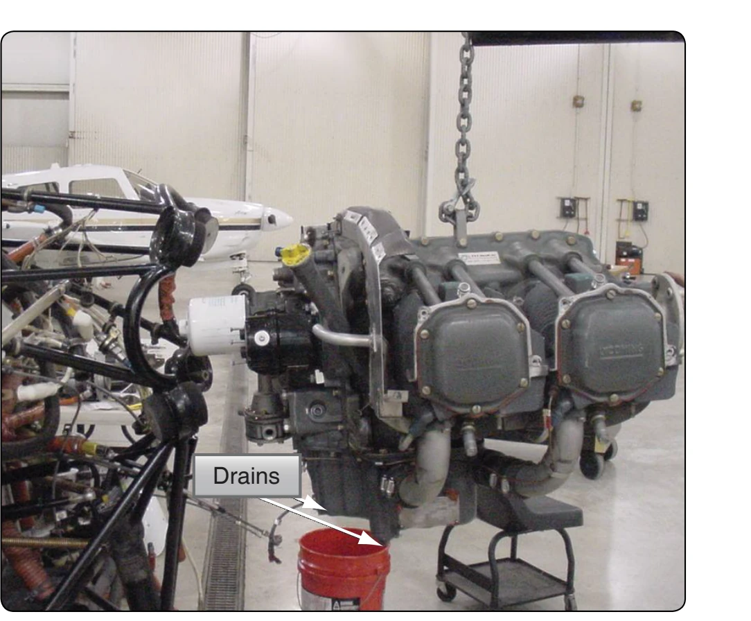
Place a large metal pan (drip pan) on the floor under the engine to catch any spilled mixture or oil. Next, secure a clean container in which to drain the oil or corrosion-preventive mixture. Place the container beneath the engine, open the drain valve, and allow the oil to drain. Figure 8-4 shows the points at which a typical aircraft engine oil system is drained. Other points at which the oil system is drained can typically include the oil cooler, oil return line, and engine sumps. All valves, drains, and lines must remain open until the oil system has been completely drained. After draining the oil, reinstall all drain plugs and close all drain valves. Then, wipe all excess oil from around the drain points.
Electrical Disconnects
Electrical disconnections are usually made at the engine firewall. When the basic engine is being removed, the electrical leads to such accessories as the starter and generators are disconnected at the units themselves. When
disconnecting electrical leads, it is a good safety habit to disconnect the magnetos first and immediately ground them at some point on the engine or the assembly being removed. Most firewall disconnections of electrical conduit and cable are simplified by use of (Army/Navy) AN or (Military Standard) MS connectors. Each connector consists of two parts: a plug assembly and a receptacle assembly. To prevent accidental disconnection during airplane operation, the outlet is threaded to permit a knurled sleeve nut to be screwed to the outlet and then fastened with safety wire, if necessary.