Chapter 5
Inspection and Packing
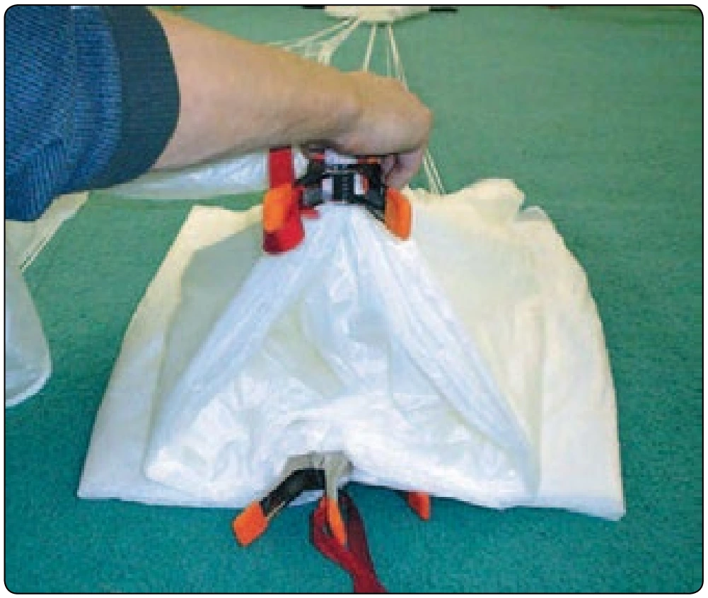
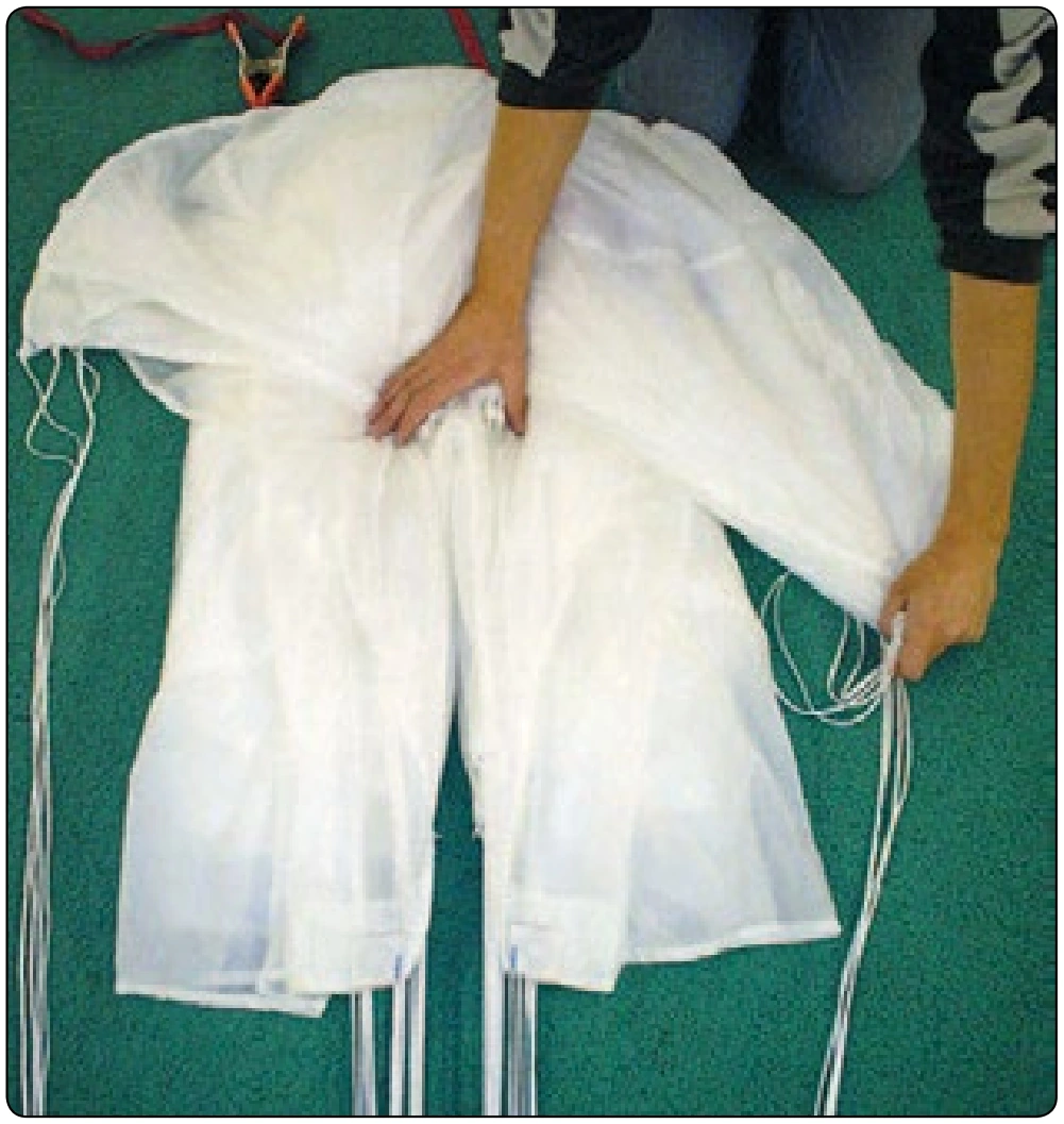
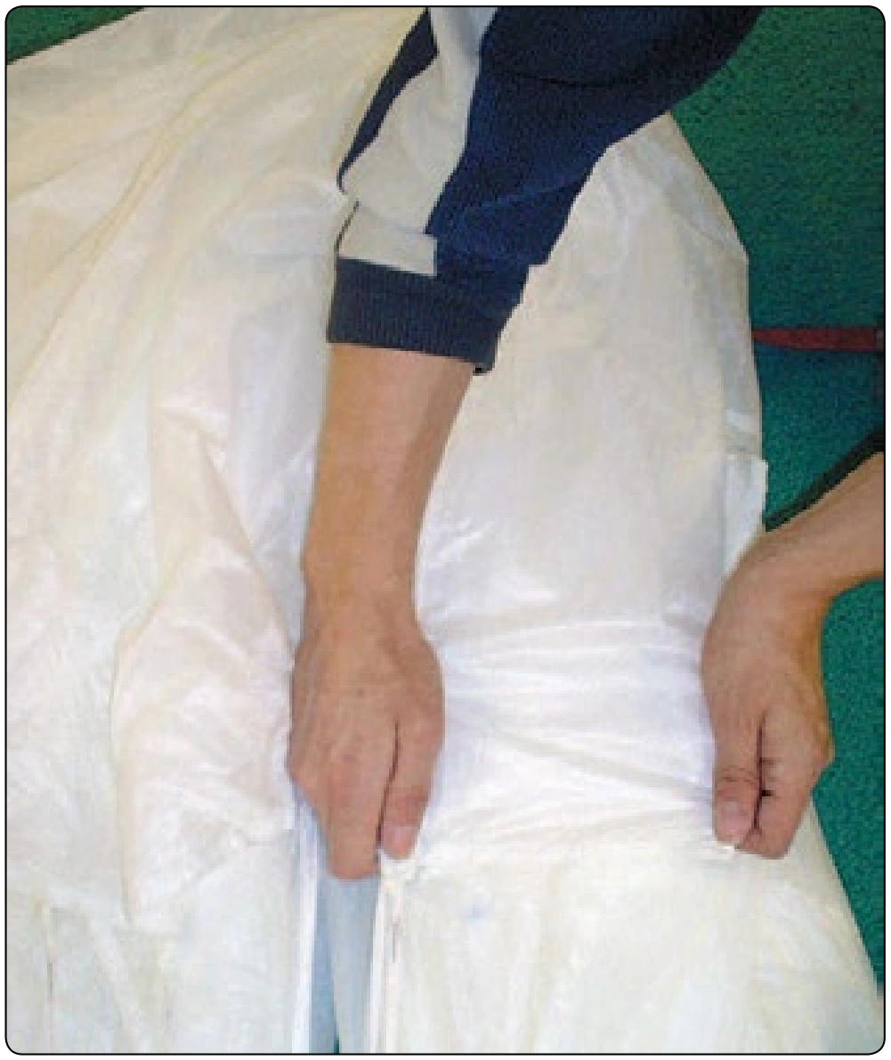
- Split the trailing edge and separate the control lines into right and left groups. [Figure 5-82]
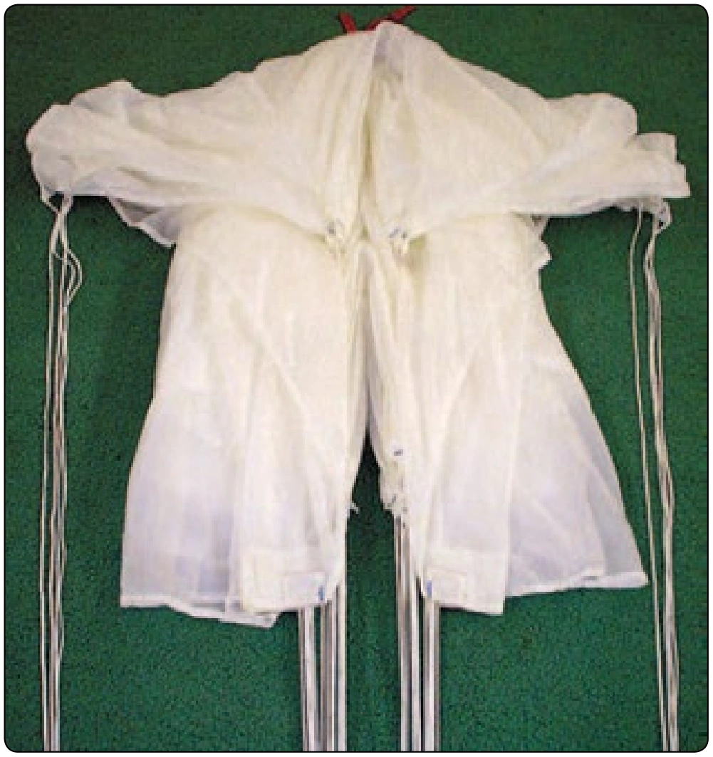
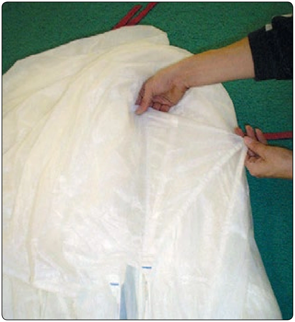
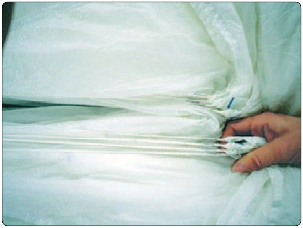
- Remove the “D” clamp. Hold down the “D” lines at the line attachment point and pull down the control lines. [Figure 5-83] Do not disturb the center of the canopy stack.
Step 3. Setting the Brakes
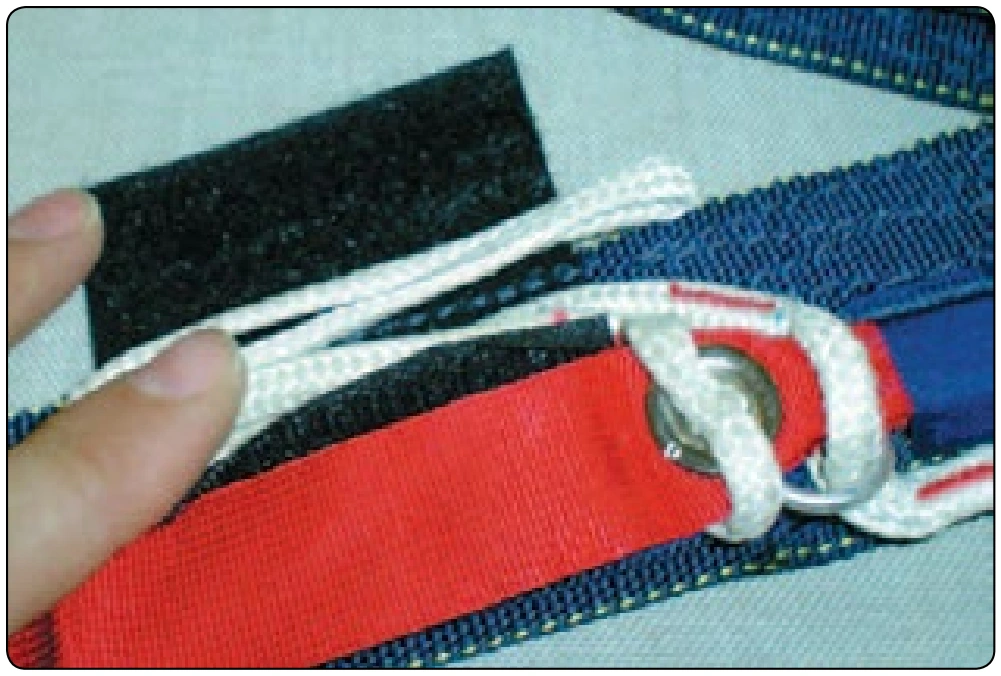
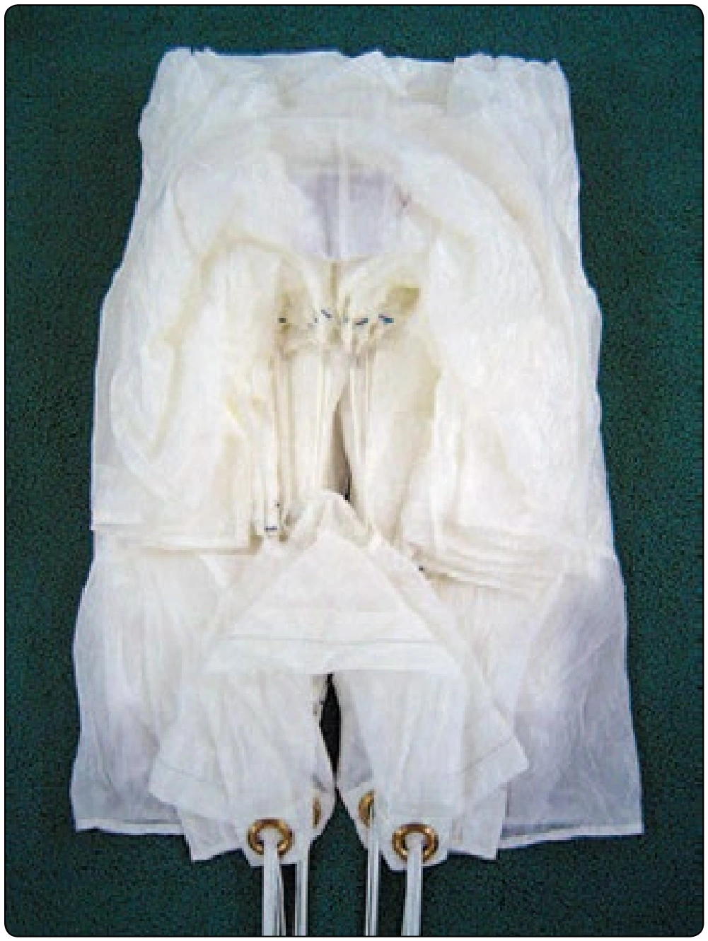
- Set the deployment brakes and stow the excess line in the Velcro® keepers. [Figure 5-84]
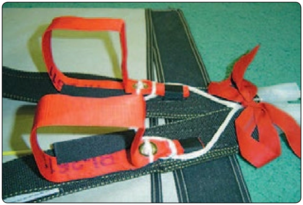
- The finished toggles should look like Figure 5-85.
Step 4. Folding the Canopy
- Fold all the trailing edge to one side, then pull the stabilizer panel taut. [Figure 5-86]
- Flake the trailing edge of the canopy starting with the outboard control lines. Fold each cell in half on top of the “D” line group until you get to the center. [Figure 5-87]
- Repeat with the opposite side.
- Pull the slider up to the slider stops.
- Remove remaining clamps from top of canopy. Make sure all suspension lines are in the center of the canopy stack. [Figure 5-88]
- Fold the center of the trailing edge back to expose the center of the wind channel. [Figure 5-89]
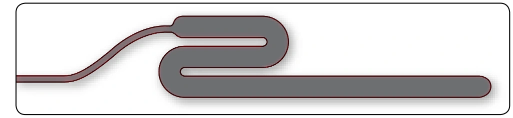
- Create an “S” fold in the stack. [Figure 5-90]
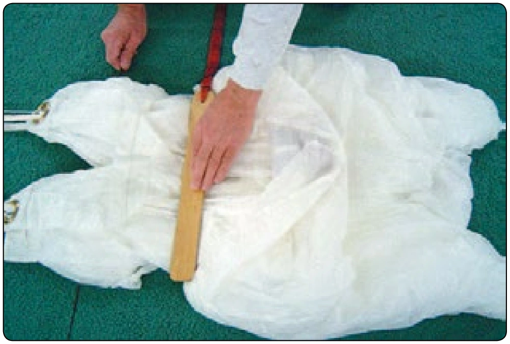
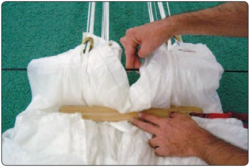
- Position a packing paddle a third of the way up from the bottom of the canopy length on top of the stack. [Figure 5-91]
- Place a gun cleaning rod at half the distance between the bottom and the packing paddle under the stack.
- Pull the rod up and move the canopy with paddle towards container. [Figure 5-92]
- Pull the top center cell panel down to the bottom of the stack.