Chapter 7
Repairs, Alterations, and Manufacture
Reassembly
- Cut the replacement Velcro® to the correct length.
- Glue the Velcro® pieces to their respective locations on the inside of the webbing.
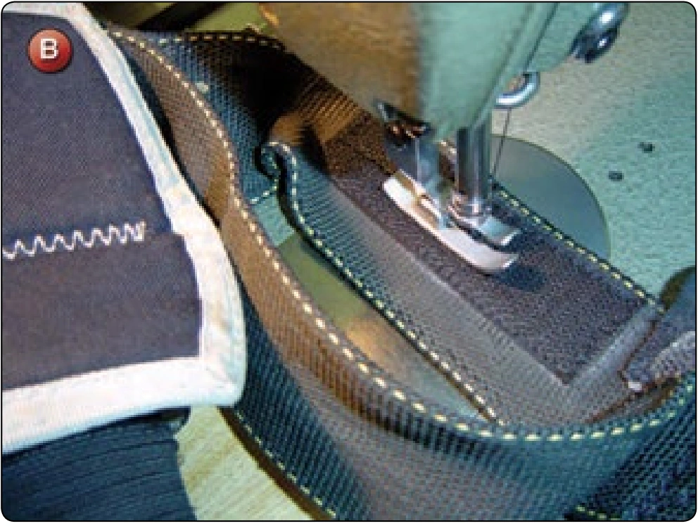
- Using the single needle machine, sew around the perimeter of the Velcro®, as well as a row of stitching down the center. [Figure B] Repeat for the opposite side.
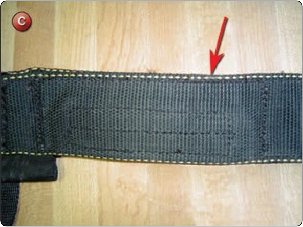
- Re-sew the pocket with two rows of single needle stitching with E thread. [Figure C]
- Reattach the harness to the backpad.
- Reinstall the ripcord housing to the harness.
Inspection
- Verify the correct orientation of the Velcro® in the pocket.
- The correct stitch pattern must be used for the Velcro®.
- Verify the ripcord pocket is re-sewn.
- The backpad must be reattached (if needed).
- The ripcord housing must be reinstalled.
Articulated Upper Leg Hardware Replacement
- Applicable products: Most articulated harness configurations
- Description: Replacement of the upper leg strap hardware
- Authorized repairmen: FAA Master Parachute Rigger
- Materials: E thread—color to match; 5-cord nylon thread—color to match; Type-8 webbing—color to match; Type-12 webbing, Type-4 1-inch tape, replacement adapter—MS-22040
- Machines: 301 straight stitch—medium duty 7–11 SPI, 308 zigzag—medium duty 7–11 SPI, heavy-duty harness machine—Singer 7–33 or equivalent, stitch to match the original
- Equipment: Scissors, seam ripper or scalpel, marking pencil, ruler, glue gun, and 4-point W-W pattern template
Procedure
The following procedure is required when the knurling on the friction bar has worn to the point that the leg strap would slip on opening. In addition, the webbing at the ring location shows wear and is replaced at the same time. This procedure is typical for a Flexon and Talon 2 articulated harness configuration.
Disassembly
- Remove the leg pad assembly.
- Remove the leg strap by cutting the webbing.
Reassembly
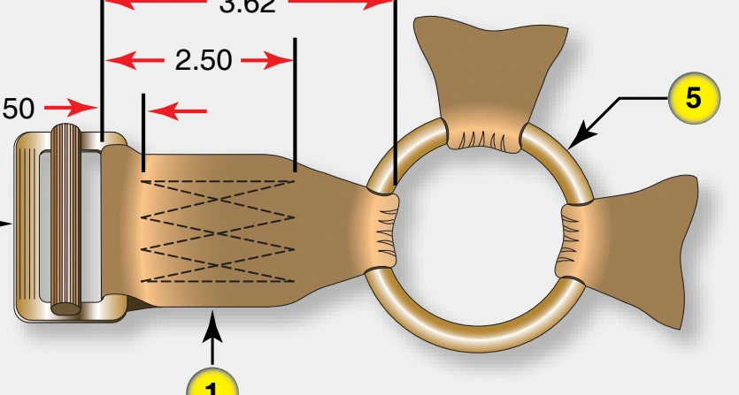
- Use Figure A to cut a replacement leg strap and parts.
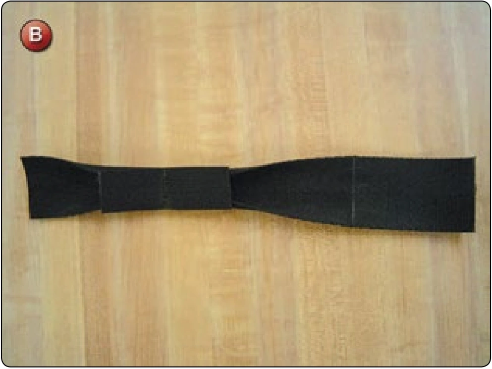
- Take the Ty-8 webbing and sew a bowtie fold with the Ty-4 tape buffer at the 3.50 inch mark. [Figure B]
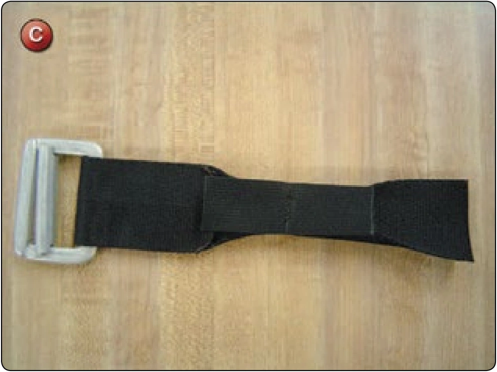
- Turn the adapter upside down and install the Ty-8 webbing as shown and glue in place. [Figure C]
- Install the bowtie around the ring and glue in place. [Figure D] The picture shows the inside orientation of the harness.
- Double check the correct orientation of the hardware. [Figure E]
- Mark the stitch pattern. [Figure F]
- Sew the webbing with the harness machine in a 4-point W-W pattern [Figure G]
- Reinstall the leg pad. Route the upper pad flap through the adapter from the bottom and zigzag. [Figure H]
- Fold the bottom pad under and zigzag in place. [Figure I] Note that the ends of the upper and lower pads are offset to reduce the thickness to be sewn.
Inspection
- Verify the hardware orientation is correct.
- Verify the stitch pattern is correct.
- The leg pad must be reinstalled correctly.