Chapter 7
Repairs, Alterations, and Manufacture
Step Three
After the teardown and cleanup, the replacement webbing can be measured, cut, and pre-sewn in preparation for installation to the harness assembly. The construction sequence is followed. In certain cases, it may be desirable to replace not just damaged parts but worn ones to give the final result a more cosmetic appearance. An example is when replacing a main lift web, it does not look good to reuse the old chest strap webbing when the main lift web is new material.
Step Four
After the repair is completed, a thorough quality control program is undertaken. This is especially critical in a situation where the rigger is working alone and there is no one to rely on for crosschecking the work. All the critical points of the repair must be identified and checked as well as the finished dimensions.
Procedure
Disassembly
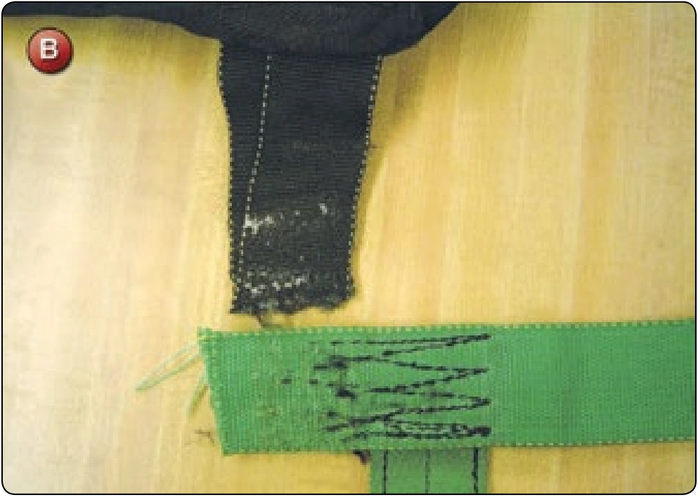
- Remove all housings, leg pads, and any other parts that may interfere with the work from the harness. Disassemble the leg strap/horizontal back strap junction. [Figure B] Disconnect the upper MLW from the yoke portion of the backpad if necessary.
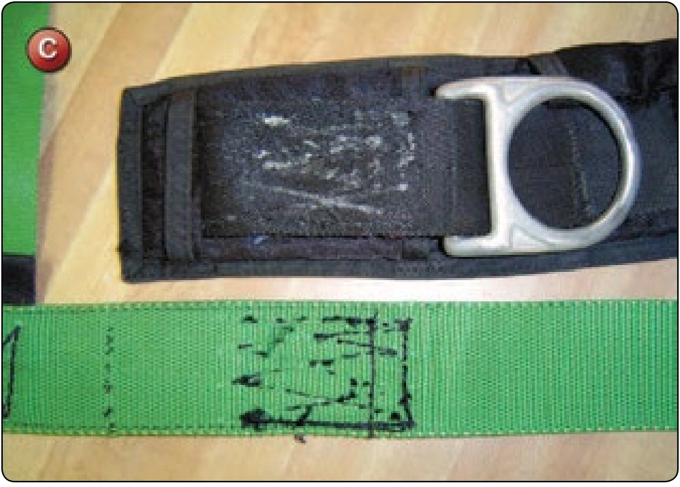
- Disassemble the junction of the diagonal back strap and main lift web at the 3-ring attachment point. [Figure C] Be very careful not to damage the diagonal back strap. If it is damaged, it is a major project to replace this on most assemblies.
- Lay out the main lift web assembly and check the measurements against the initial dimensions. Check against the opposite side MLW for symmetry.
- If this side of the harness has a TSO or identification label attached, carefully remove it for use on the new assembly. If it is damaged, it may be necessary to get a new label to replace it. Contact the manufacturer for guidance. They may require the rigger to return the old label in exchange for a new one.
Reassembly
- Note that this configuration consists primarily of two main pieces of webbing. The front MLW is Type-7 webbing and the rear is Type-8.
- Measure the new webbing for the main lift webs. Add 5 inches for the riser end fold back and allow at least 6 inches extra for shrinkage. While this may sound like a lot, nothing is more discouraging than to get to the end of the project and find that the webbing is short by an inch or two. A couple inches of scrap is a small price to pay at this point.
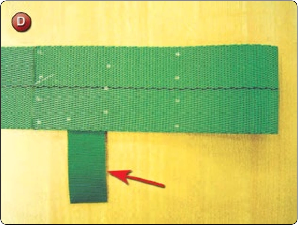
- Starting at one end of the webbing, measure the riser end configuration. Fold back and glue in place. If there is a toggle stow loop on the old harness, do not forget to glue in place before sewing. [Figure D] Mark the 4 point W-W pattern and sew with the harness machine and 5-cord nylon thread.
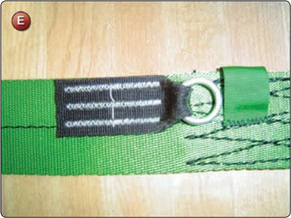
- Install the steering line guide ring with a duplicate stitch pattern as per the original. [Figure E] In some instances, the manufacturer may have used a special bar tack or other stitch pattern to attach the ring. If the rigger does not have the same machine, it is necessary to contact the manufacturer for an acceptable alternative. This should have been identified in phase one. Check the distance from the end of the riser to the top of the ring. The industry standard is 4 inches, but there may be special dimensions for some applications.
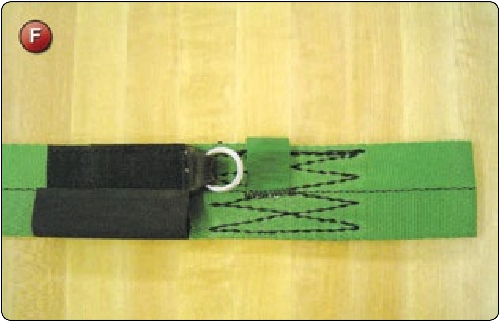
- Install the toggle Velcro® keepers as per the original. [Figure F] Complete any other sewing needed, such as the end of the toggle stow loop.
- If needed, reattach the TSO label at the appropriate location. If the label is the original one and is made from material such as Ty-vek®, try to follow the original needle holes to avoid perforating the material. Too many holes cause the label to tear out.
- Working from the measurement diagram in Figure A, mark the location of the 3-ring.
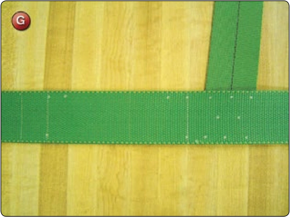
- Working downward mark the location of the chest strap, the ripcord pocket, and the bottom of the upper leg strap. [Figure G]
- The harness stitching at the 3-ring.
- The harness stitching at the chest strap.
- The ripcord pocket.
- The harness stitching at the leg strap junction.