Chapter 7
Repairs, Alterations, and Manufacture
The standard rule of thumb for the sum of these patterns is approximately .75 inch for the length. In other words, the marked length of the MLW should be .75 inch longer than the desired finished length. Most of the shrinkage is in the ripcord pocket and the leg strap junction. If the rigger has not done this operation before, he or she may want to build a sample MLW to check the measurements and the resultant shrinkage.
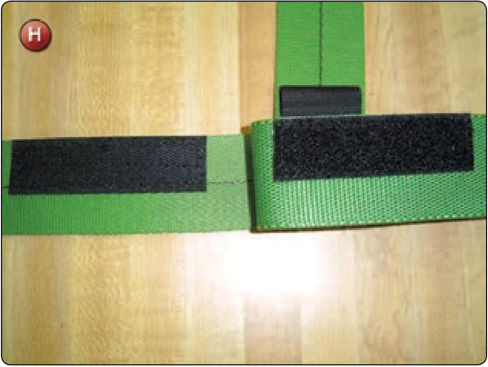
- Sew the Velcro® in place for the ripcord pocket. [Figure H]
- Glue the chest strap in place. In this instance, do not forget the housing loop.
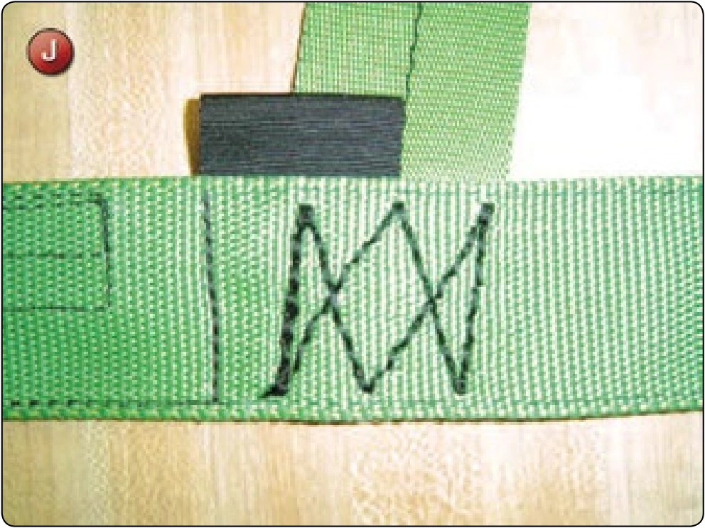
- Using the single needle, pre-sew the front and rear main lift webs. Use of the sewing pattern in Figure I accomplishes this and at the same time creates the ripcord pocket. Sew the chest strap 3-point W-W with the harness machine. [Figure J]
- Reassemble the upper diagonal back strap and the 3-ring hardware by threading the rear riser through the large ring followed by the front riser.

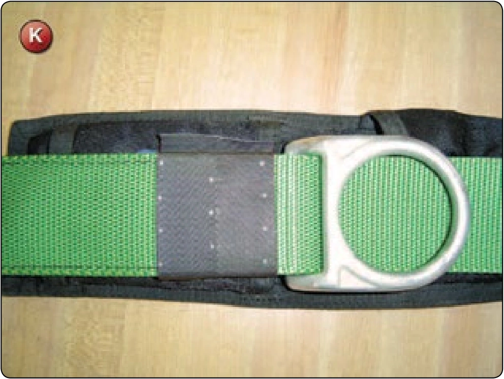
- Position the 3-ring at the mark on the main lift web and glue in place. Install the Type-12 confluence wrap below the 3-ring and mark the 4-point W-W pattern. [Figure K]
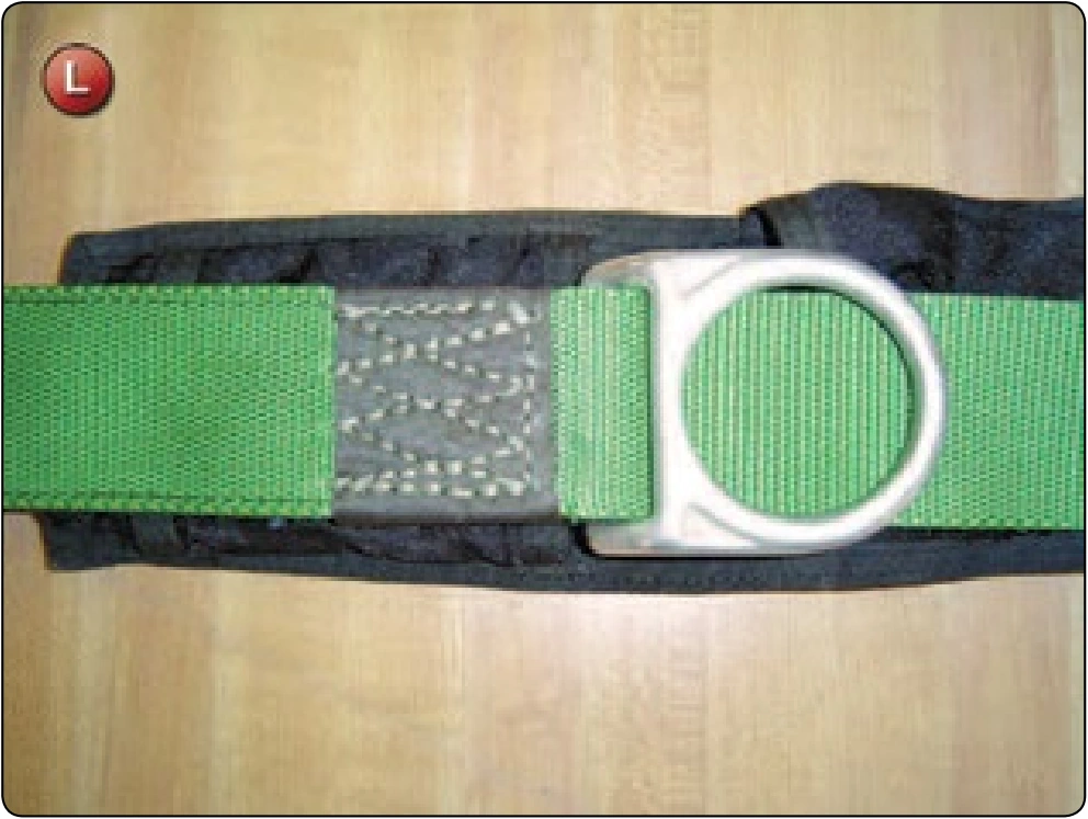
- Sew the confluence wrap with the harness machine. [Figure L]
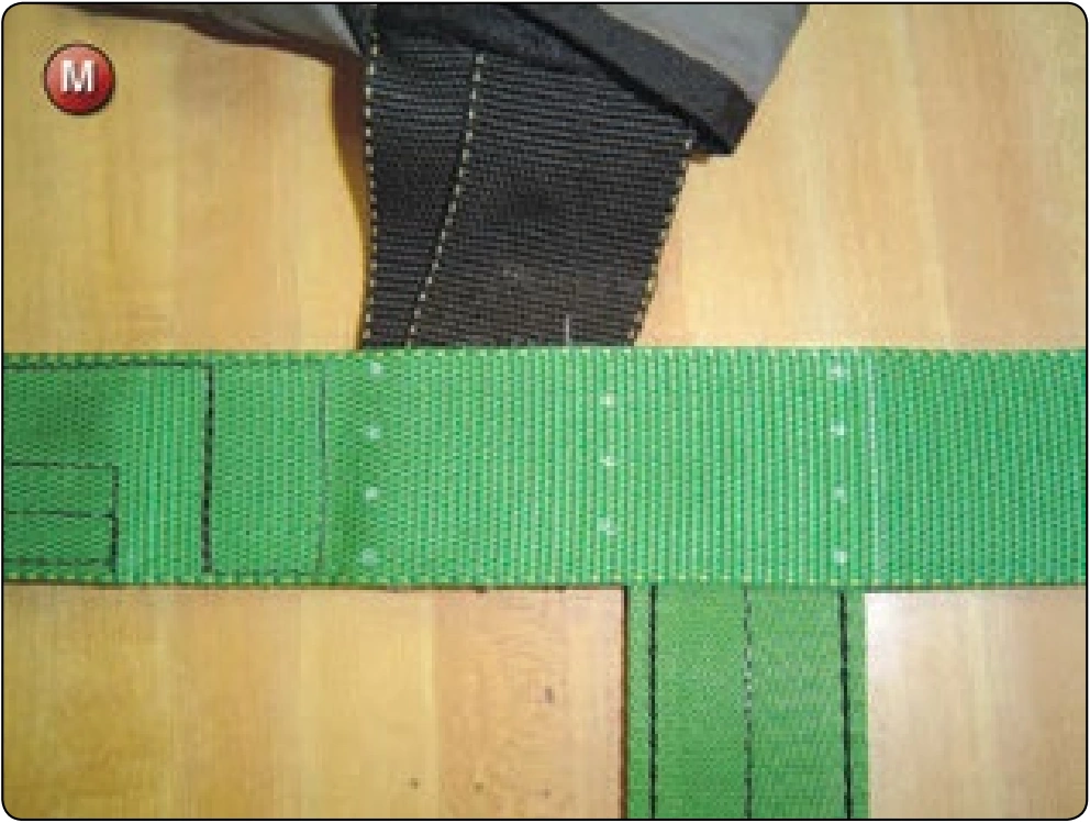
- Re-create the leg junction. Glue the upper leg strap in place first and then the horizontal back strap second. [Figure M]
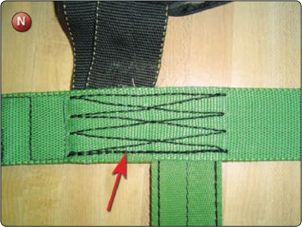
- Mark the 4-point W-W and then sew with the harness machine. Start the stitch pattern at the front side of the MLW and complete with the overstitch the full length of the pattern. [Figure N] This provides additional reinforcing at the upper leg strap/MLW location.
- Measure the length of the lower leg strap allowing 3.50 inches for the rolled stop end. Trim to length and then install the stop end with the harness machine.
- Reattach the backpad to the upper MLW using the 308 zigzag machine.
- Reinstall the leg pads using the 308 zigzag machine.
- Reinstall the ripcord and 3-ring housings and hand tack in place.
Inspection
- Check the finished dimensions against the original dimensions in Figure A. If only one side has been replaced, check the new MLW against the opposite side for comparison. The generally accepted tolerances for this type of construction are ± .25 inch. In particular, reserve riser length and the overall MLW length are the most important. If either of these is mismatched to their opposites, then the flight of the canopies may be affected.
- Start inspecting from the riser end working down. Use the inspection chart in Figure O as a guide for the inspection points. After the inspection, all appropriate paperwork must be completed. This includes the rigger’s logbook, the packing data card for the parachute, and any shop or business forms or log.
Main Riser 3-Ring Locking Loop Replacement
- Applicable products: All 3-ring riser assemblies
- Description: Replacement of the 3-ring riser locking loop
- Authorized repairmen: FAA Senior or Master Parachute Rigger
- Materials: E thread; 5-cord nylon thread—color to match, Type-IIa nylon cord or equivalent
- Machines: 308 zigzag—medium duty 10 SPI and heavy-duty harness machine—Singer 7–33 or equivalent Equipment: Scissors, seam ripper or scalpel, marking pencil, 6-inch ruler, glue gun, and hot knife
Procedure
Disassembly
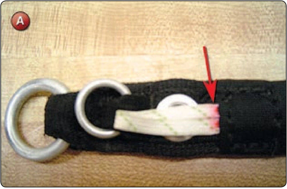
- Mark the locking loop at the bottom edge of the confluence wrap. [Figure A]