Chapter 7
Repairs, Alterations, and Manufacture
Inspection
- Check that the location of Velcro® is the same as the original.
- Check stitch patterns and center stitching.
Section 4, Accessory Components
Accessory components are comprised of the reserve pilot chute, reserve deployment bag or device, main deployment bag, main pilot chute and bridle, main and reserve toggles, reserve static line (RSL) lanyard, 3-ring release handle, and reserve ripcord.
The reserve components generally do not suffer much wear due to their infrequent use. In addition, with their frequent inspection during the repack cycle, any necessary repairs become obvious and are taken care of before they become major problems.
- Metal ripcords usually are not repairable and must be replaced when they are damaged.
- Reserve pilot chutes experience torn mesh, minor canopy damage, broken hand tackings, and damaged grommets in the cap.
The reserve free bag may have the grommets in the closing flap pull out of the material. The high-drag bridle is a critical area and is usually not repairable. The RSL lanyard is another critical item that is usually not repairable, except for the replacement of a defective snap shackle.
Main components, on the other hand, are subject to extensive wear and tear. Most jumpers do not take time to inspect their main components on a regular basis and generally operate on a “repair as broken” basis. By the time the rigger sees the components, it is easier and more cost effective to replace than to repair them. However, there are regular wear trends that the rigger can make their customers aware of so they can look for them and have them taken care of.
The following are repairs to accessory components, found in Section 4, Accessory Components, of this chapter:
- Reserve pilot chute repair—mesh, tackings, and bad grommet
- Reserve free bag repair—grommet pullout
- Main pilot chute repair—top canopy reinforcing
- Main pilot chute collapsible bridle replacement
- Main deployment bag repair—closing flap grommet pullout
Reserve Pilot Chute Repair—Mesh, Tackings, and Bad Grommet
- Applicable products: Most reserve pilot chutes
- Description: Replacement of cap grommet
- Authorized repairmen: FAA Master Parachute Rigger
- Materials: Nylon supertack, stainless steel sheet grommet—same as original
- Machines: None
- Equipment: Scissors, seam ripper or scalpel, hand tacking needle, grommet set, and diagonal cutters
Procedure
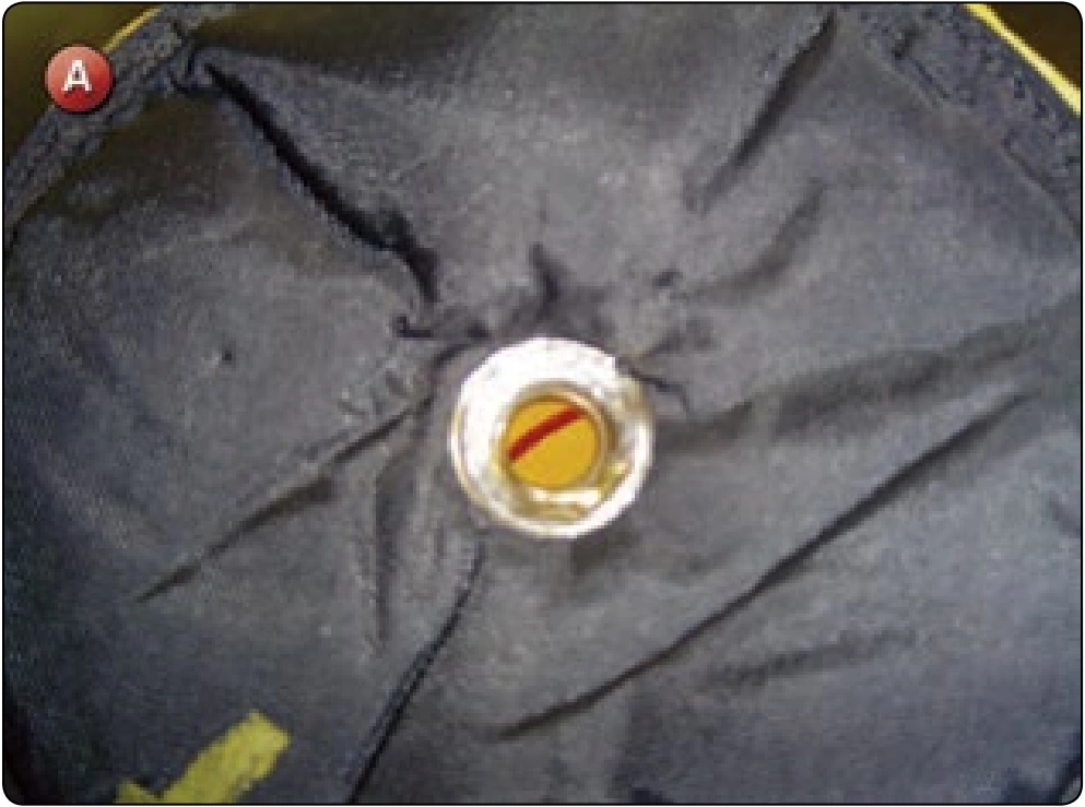
The canopy fabric portion of a reserve pilot chute would be repaired as necessary with similar patching techniques as used on a canopy. The mesh portion, however, may be subject to different techniques. Another area of common damage is the thru grommet in the top of the pilot chute. The following procedure describes the replacement of the grommet in the top of the pilot chute. Figure A shows a damaged grommet.
Disassembly
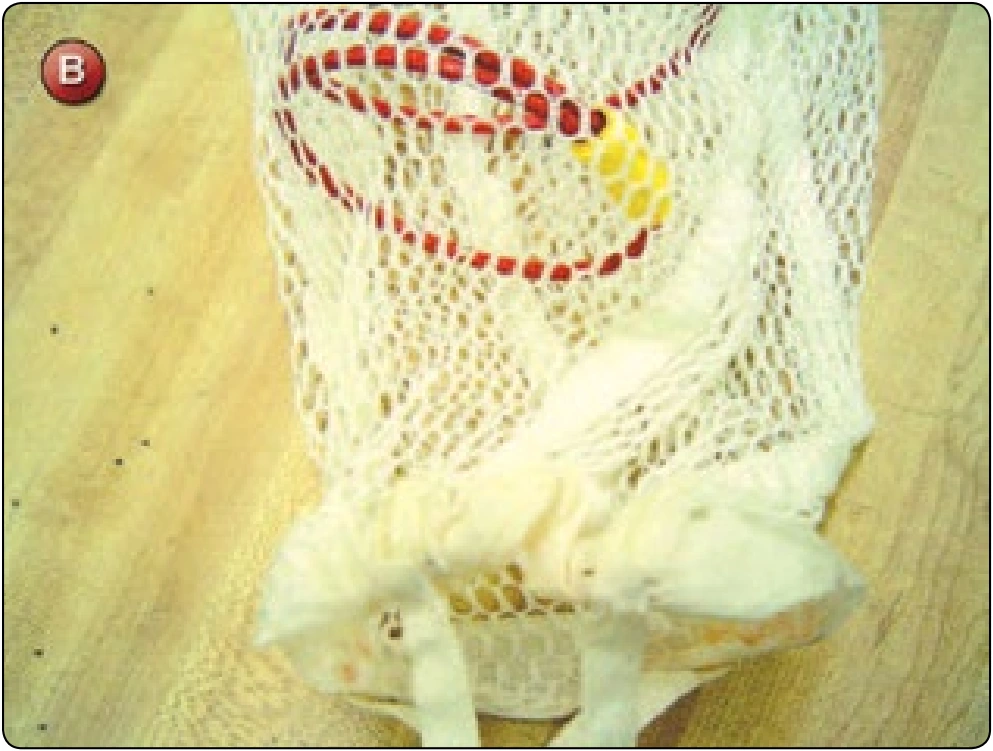
- Remove the hand tackings used to secure the base of the pilot chute to the spring. [Figure B]
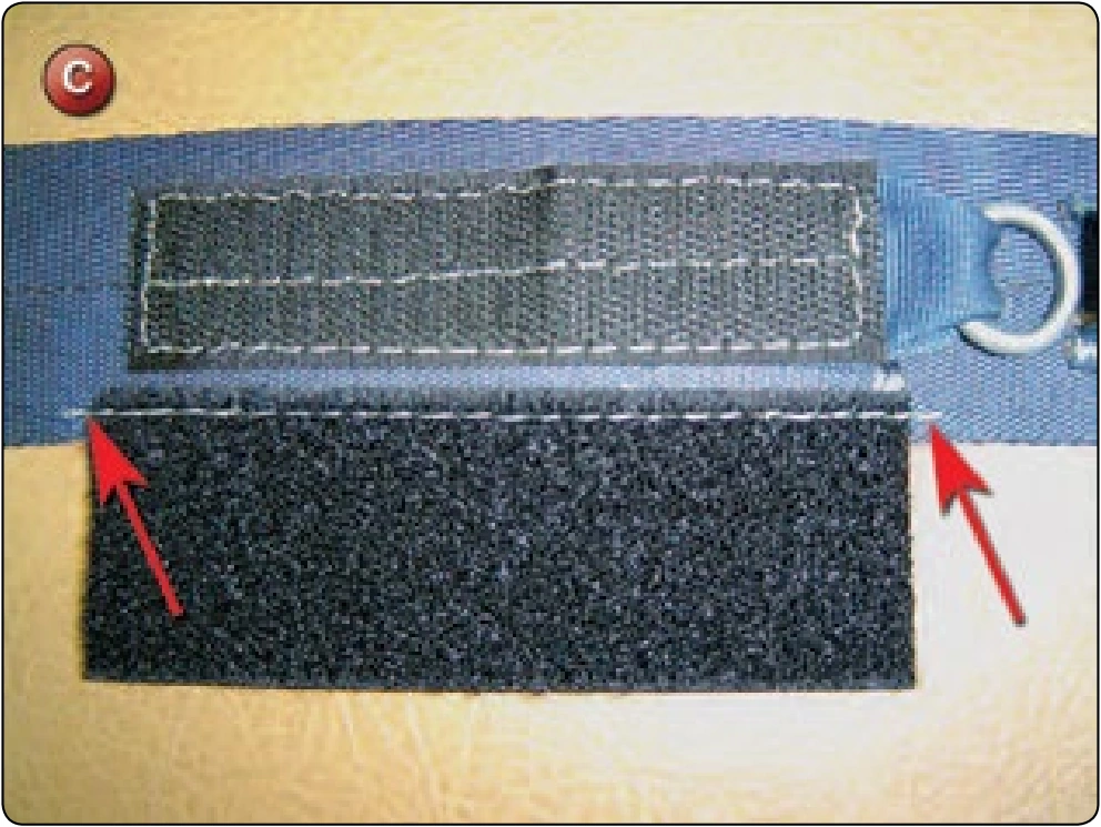
- Turn the pilot chute upside down and push the canopy down until the grommet is exposed. [Figure C]
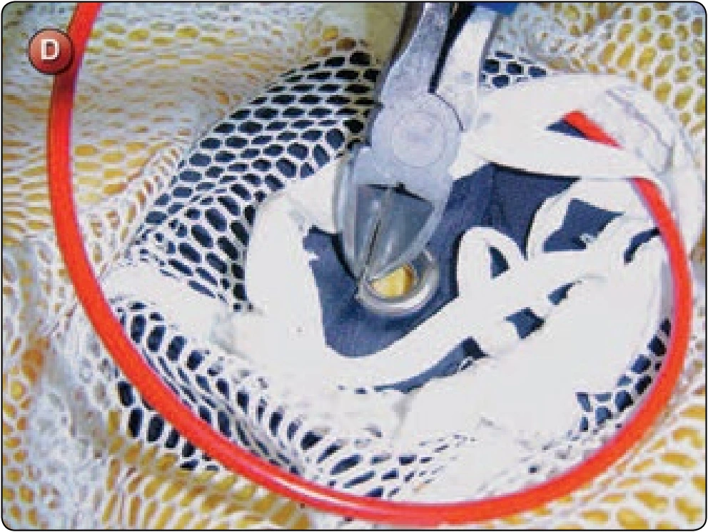
- Using diagonal cutters, remove the damaged grommet being careful not to damage the fabric of the cap. [Figure D]