Chapter 7
Repairs, Alterations, and Manufacture
Reassembly
- Using the double needle machine and binder, bind the end of the sleeve. [Figure D]
- Sew the sleeve to the pad and pre-sew the foam with the single needle.
- Trim the ends of the tape.
- Rebind the pad starting at the upper corner. [Figure E] Make sure the inside curve of the pad is fully captured by the binding.
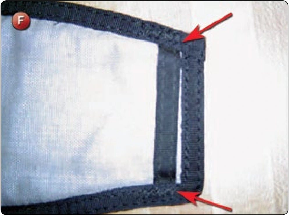
- Bar tack at the original locations. [Figure F]
Inspection
- Verify the length is correct.
- Check that the bar tacks are at the original location.
Automatic Activation Device (AAD) Installation
- Applicable products: Most 1-pin sport piggyback systems
- Description: Installation of a CYPRES® AAD to a 1-pin sport piggyback harness and container system
- Authorized repairmen: FAA Master Parachute Rigger
- Materials: E thread—color to match, CYPRES® installation kit, and Spandex® fabric (optional)
- Machines: 301 straight stitch—medium duty 7–11 SPI and 308 zigzag—medium duty 7–11 SPI
- Equipment: Scissors, seam ripper or scalpel, marking pencil, 12-inch ruler, hot knife, and wallpaper roller
Procedure
The following procedure is representative of a typical installation of the CYPRES® AAD into a modern 1-pin reserve container system. While providing guidance for this operation, it is imperative that the rigger possesses the proper instructions from both the harness-container manufacturer and the AAD manufacturer.
Disassembly
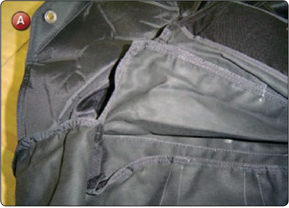
Open the right side corner of the reserve container. [Figure A] While this might not be needed on some size containers, it generally makes the installation of the pocket easier and it is not that hard to close the corner back up.
Reassembly
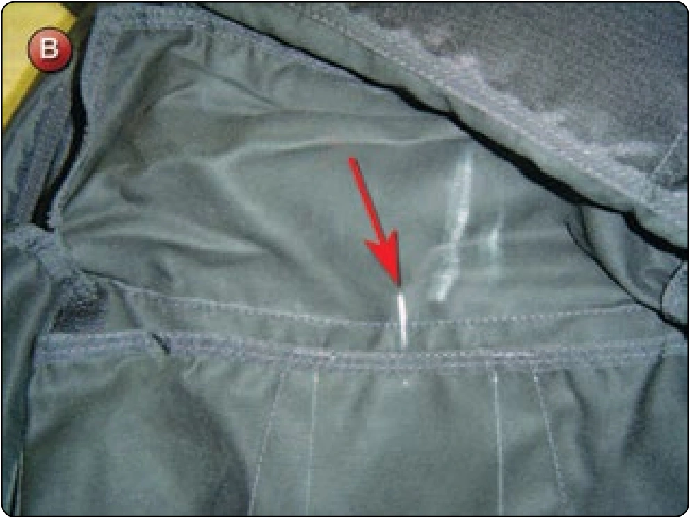
- Mark the center of the container wall at the bottom. [Figure B]
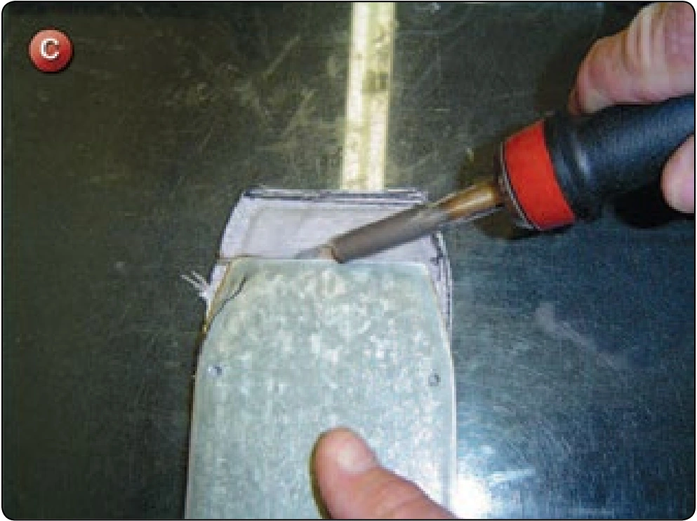
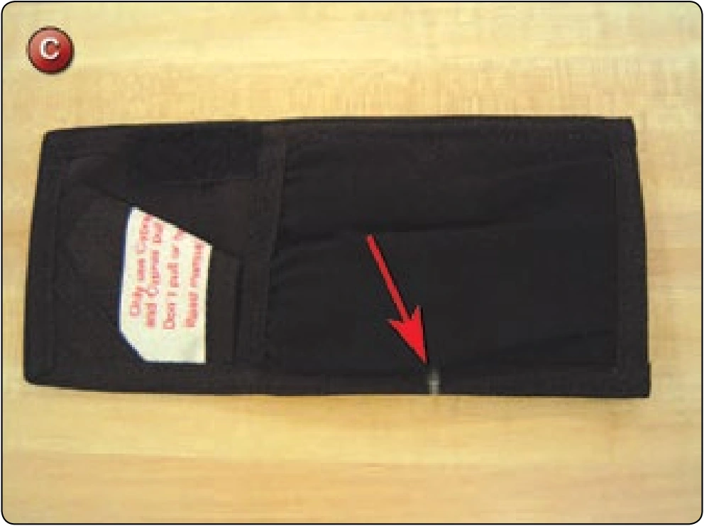
- Mark the center of the Spandex® portion of the CYPRES® pocket. [Figure C] Do not mark the center of the entire pocket. The Spandex® must be centered on the wall to allow for the correct positioning of the CYPRES® processing unit.
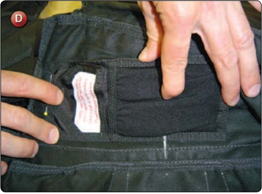
- Align the marks and the pocket as close to the bottom of the wall as possible. [Figure D]