
Chapter 7
Repairs, Alterations, and Manufacture
- Sew around the pocket with the single needle machine. Backstitch .5 inch at each of the corners for reinforcing.
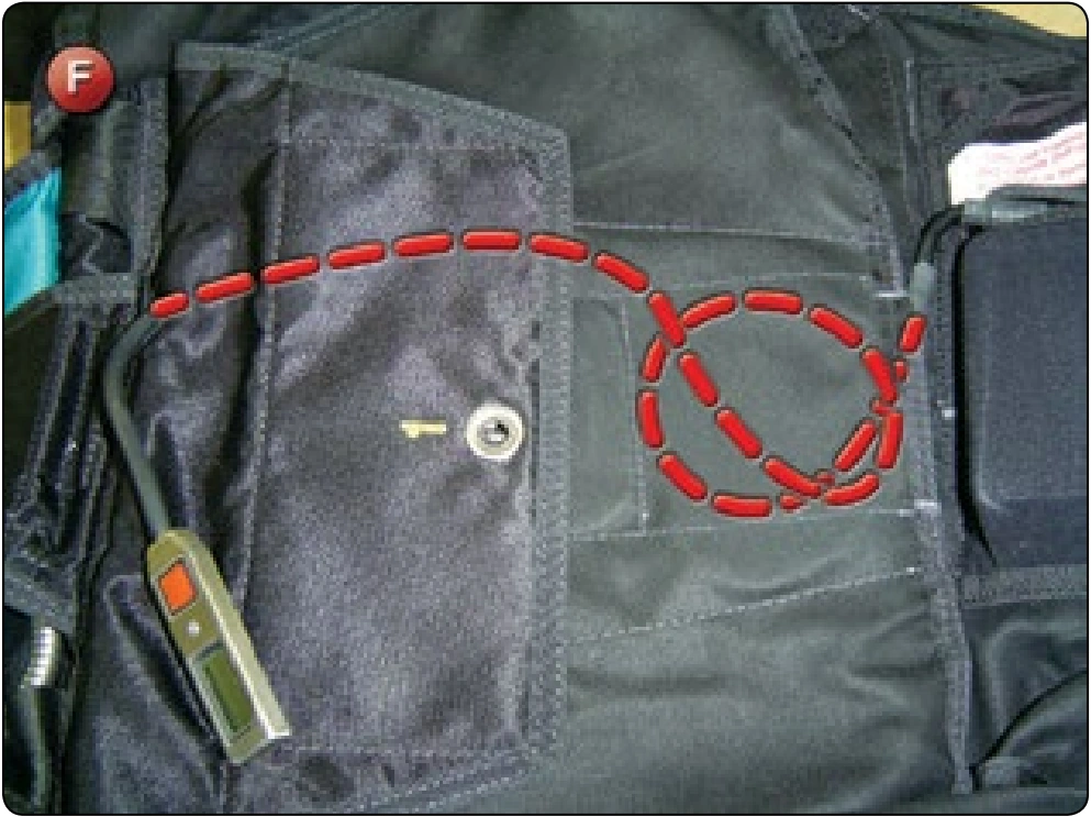
- Next, install or create a cable channel for the control cable. Some systems, such as the one shown in Figure F, can be modified to provide the channel.
Others need to use the adhesive backed channel provided with the CYPRES® kit.
Built-In Channel Modification Configuration
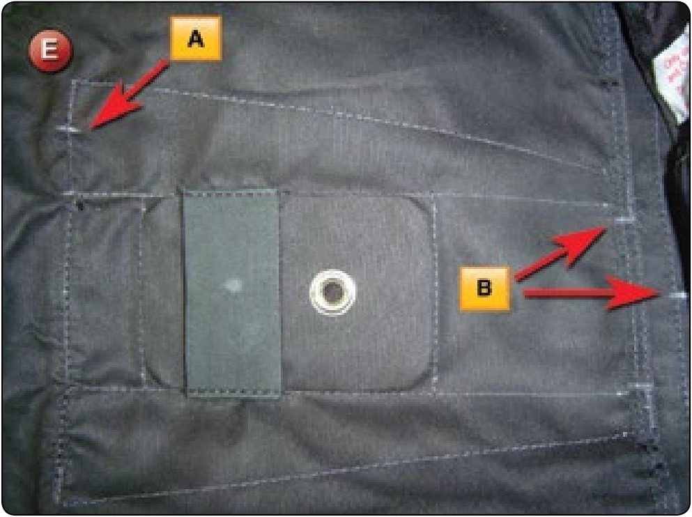
- Mark the bottom and top of the pack tray cover as shown. [Figure E] Place a hand tack at the A position. Unpick the stitching between the corner bar tack and the hand tack at the A position. Also, unpick the stitching between the B bar tacks.
- There is now a built-in channel to slide the control cable thru and stow the excess cable as well. [Figure F]
Adhesive Channel Installation
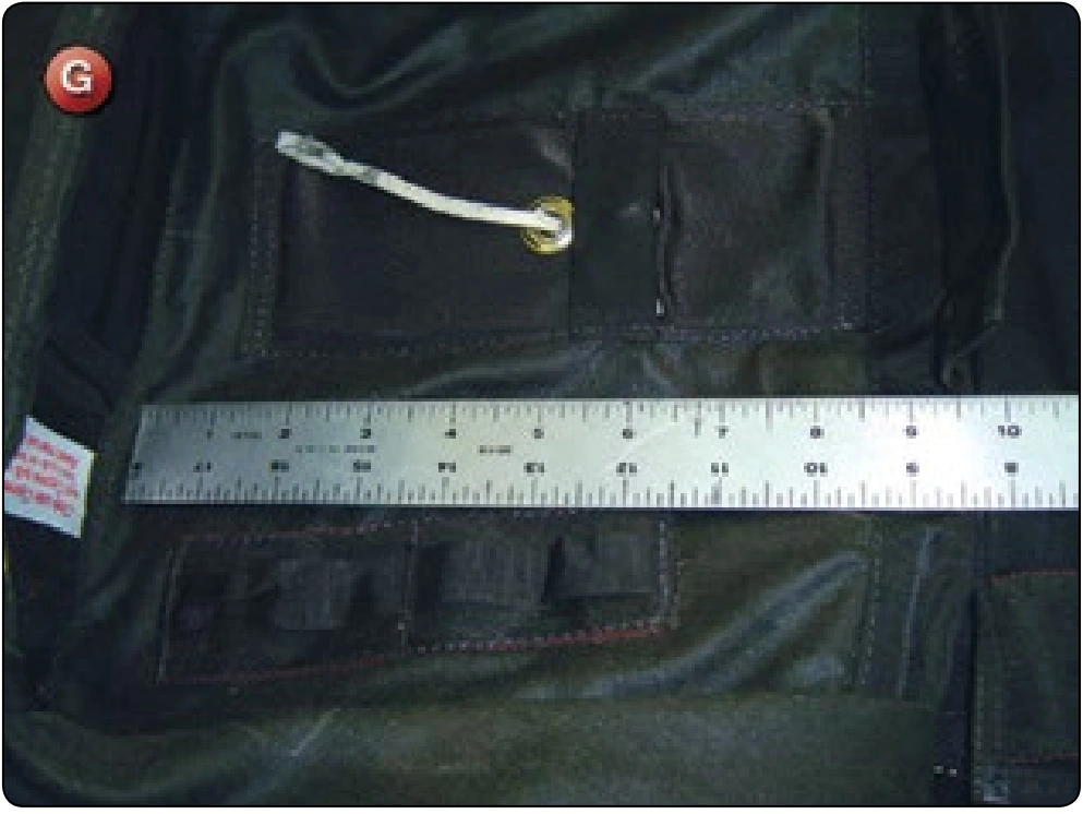
- Measure the distance along the long axis of the reserve container from the bottom of the pocket location to the top of the container near the planned location for the control unit. [Figure G]
- Cut a piece of the adhesive backed channel to the same length. Remove the adhesive covering and position the channel in place. Roll the channel with the wallpaper roller to secure the adhesive.
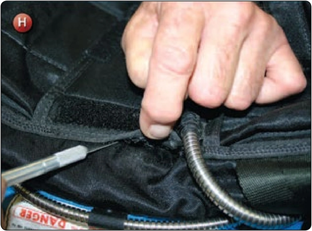
- Locate the position for the control pocket. Unpick the stitching that holds the main container to the backpad. [Figure H]
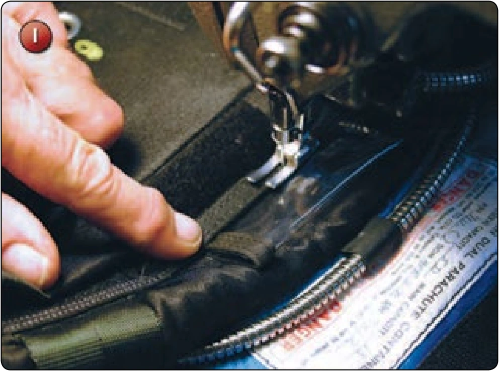
- Insert the pocket with the mouth towards the channel opening and restitch the container to the backpad. [Figure I] Make sure the control head fits into the pocket.
Cutter Channel and Elastic Installation
The location of the cutter is specified by the container manufacturer’s instructions and should be strictly adhered to. The following location is specified for the Talon system.
- Lay the CYPRES® unit on the pocket and route the cutter/cable assembly out the top of the pocket and in as direct a line to the side flap as possible. It is necessary to cut a hole in the bottom launching flap to access the side flap.
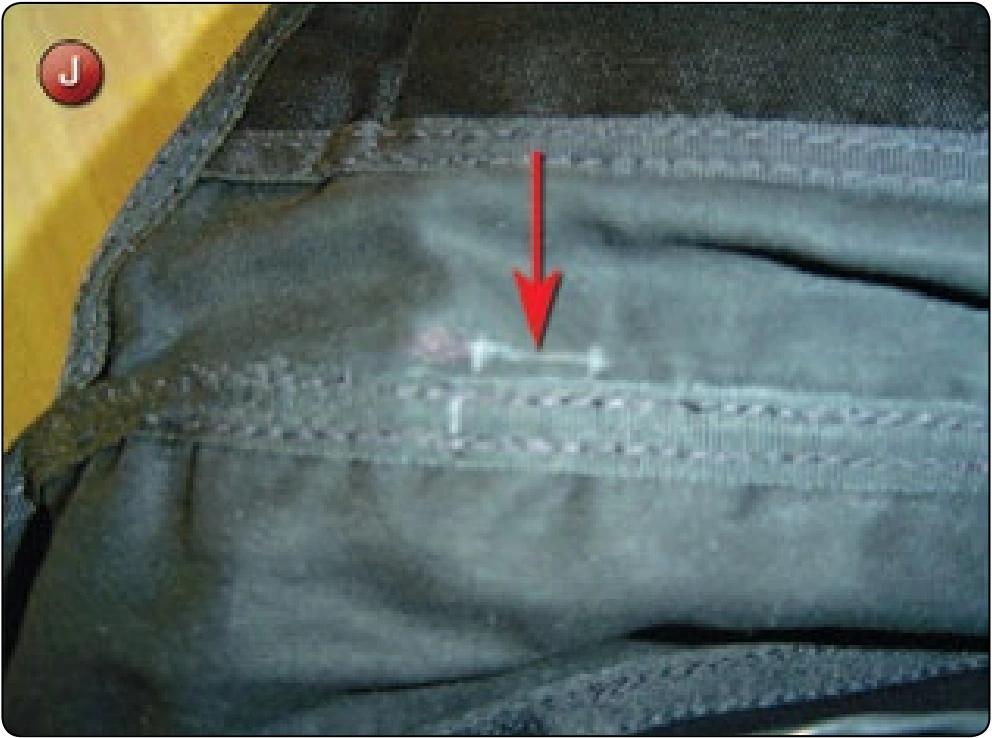
- Where the cable passes through the bottom launching flap as close to the wall as possible, place a line approximately .5 inch long. [Figure J] Take the hot knife and cut a single slit the length of the mark. DO NOT CUT ANY OTHER MATERIAL.
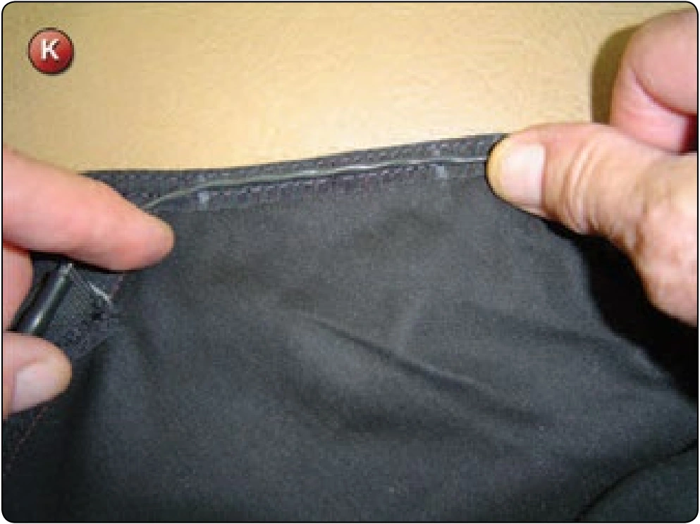
- Route the cable through the slit and then along the side flap as shown. [Figure K]
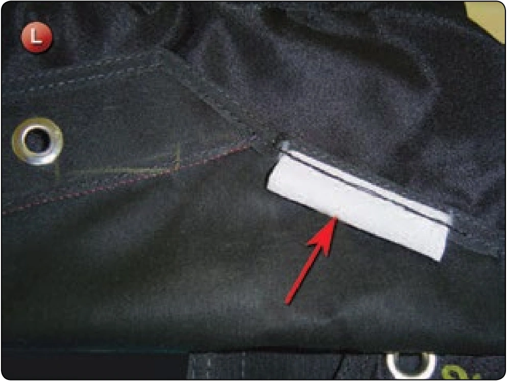
- Place marks along the binding showing the start and finish locations for the cable channel. Again, the rigger can use the adhesive backed channel or make a channel out of the Spandex® material as shown. [Figure L]
- Route the cutter thru the channel and out the end nearest the side flap grommet.
- Slide the cutter elastic over the cutter and position the cutter over the grommet with the hole to the outside of the grommet and the elastic facing inwards on the flap. Mark the corners of the cutter as shown. [Figure M]